During the past year I practically ended all ham radio related activities due to some family updates 👶 🙂
In the summer however I visited Italy again and… guess what? I had an opportunity to make another Japanese contact on 20 meters SSB, this time with JH1GEX Yutaka, near Tokyo.
Yutaka is an excellent operator: he routinely halts his pile-up to allow mobile / portable stations to make it through. If everyone would be so kind, portable operations would be much, much easier! Thank you Yutaka san!
With the help of Antonio IK6ZRX (who cut through the pile-up) I was able to work Kazu, JH3NGD with my portable loop and 10W on 20meters SSB.
Here is the video:
Unfortunately It was night and I could not properly ready Kazu’s call, so I misread it the whole time (rookie mistake). Besides that, I was given a 53 and was able to have a nice little QSO with Kazu, who speaks perfect Italian!
This obviously was a much easier QSO than It could have been because I had been announced by Antonio. Nevertheless it was for me a remarkable one. Thanks Kazu and thanks Antonio!
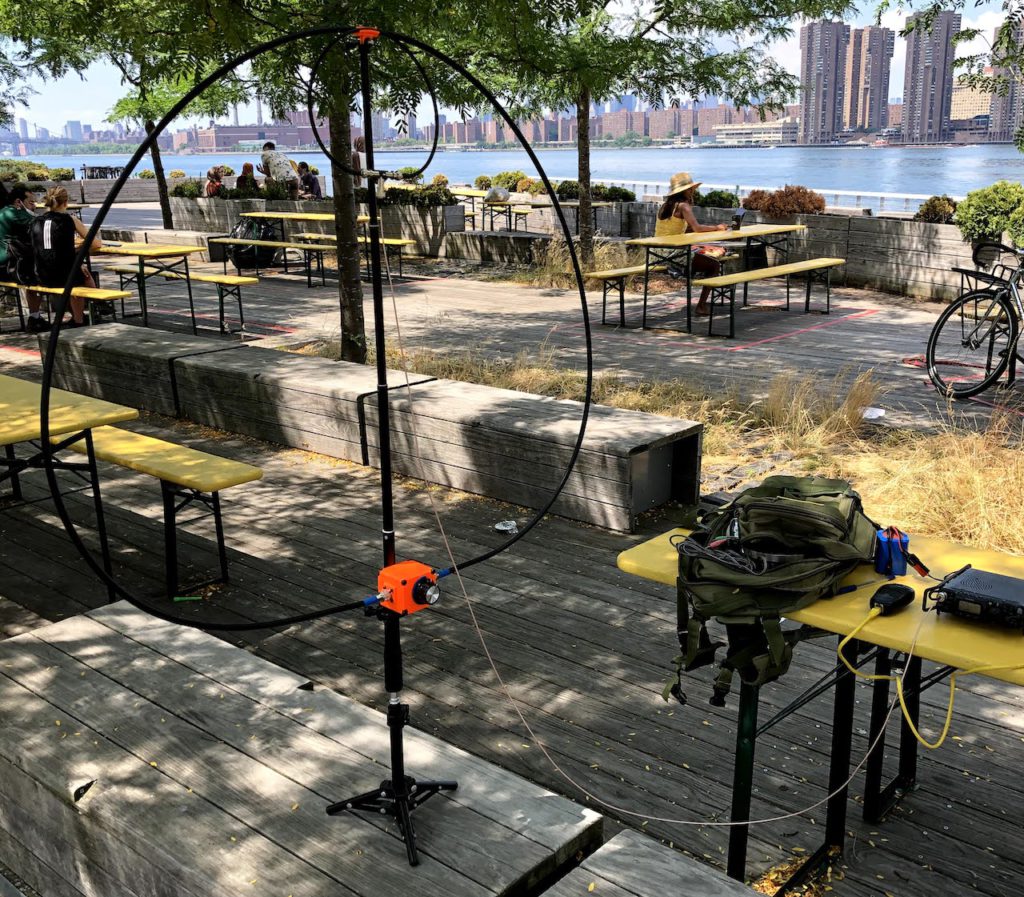
The latest version of the K1FM-Loop is electrically similar to the previous one, but it is designed around off-the-shelf parts or, more generically, items you can readily order online.
This antenna relies – heavily – on 3D printing. Acquiring the non-printed parts and assembling them should be fast and easy as no reworking at all is necessary. The needed tools are screwdrivers, wrench keys and a soldering iron. You also need a 3D printer, of course, or at least access to one.
Socket Head Cap Screw, M5-0.8mm Thread, 12mm Long, Alloy Steel, Black Oxide (8 pieces)
Button Head Socket Cap Screws, 6-32 x 5/16″, Black Oxide Alloy Steel (3 pieces)
Hex Socket Head Cap Screws Bolts, M3-0.5mm, 9mm Long, Alloy Steel , Black Oxide (8 pieces)
Hex Self Clinching Nuts, M3-0.5mm (8 pieces)
18AWG electric cable ~5 inch
M3 Ring Cable Lugs Terminals (4 pieces)
The antenna is composed of three parts that I am going to describe separately. They are:
Capacitor assembly
Radiator / Exciter assembly
Supporting structure
Let’s see them one by one:
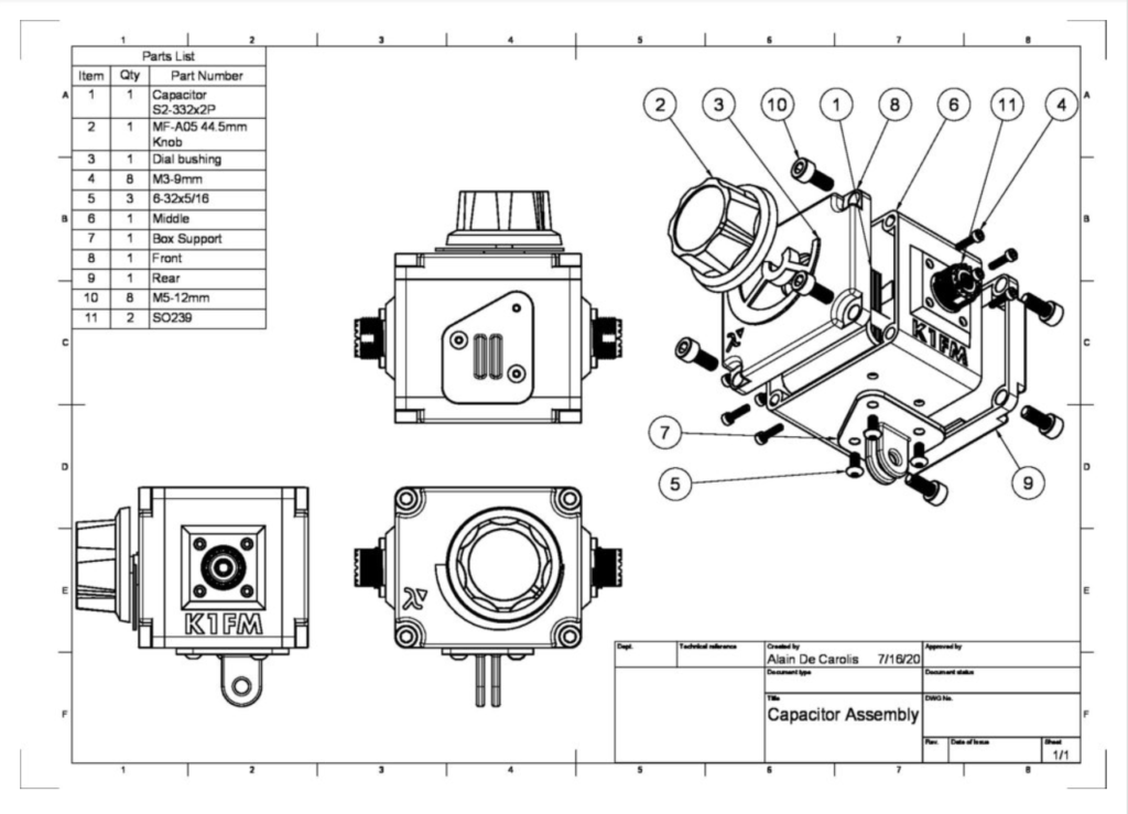
Capacitor assembly
First of all, you need to print the necessary 3D printed parts. It might be opportune to print the Dial Bushing in a different color, in order to make more visible against the rest of the box. I printed the box in PETG because of the enhanced mechanical and thermal characteristics. ABS would also be opportune I think, or even PLA (provided you are careful not to leave it inside of a burning car).
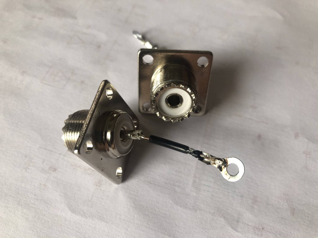
As the print goes, you can start working on the other parts. All you need to do is solder a piece of cable on each gang terminal, on opposite sides. Terminate the cable extensions with a ring contact, like so:
Optionally, you could solder the same extension on the center connector of each SO239. This will allows to use the center conductor as part of the radiator (Do I think this is useful? I don’t, but I’m going to do it to avoid the complaints). Here are the connectors, ready to be used:
The new design improves the older one in a few key aspects:
– Entirely 3D printed – Readily available, made in the USA variable capacitor – Easyto assemble
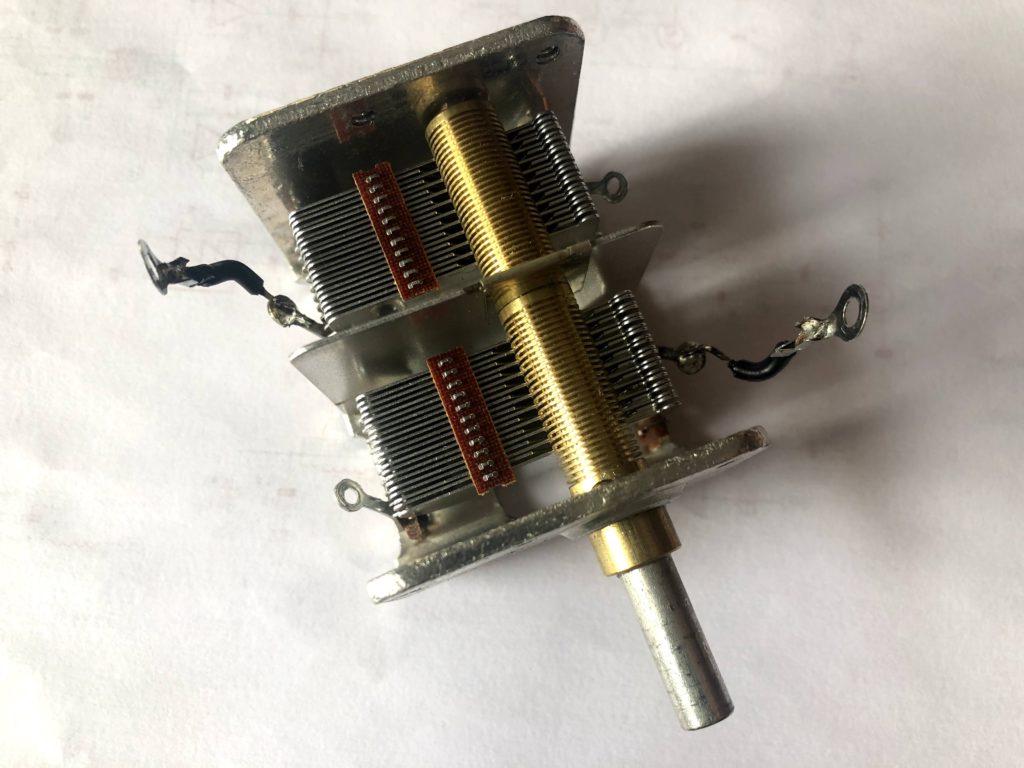
Basic geometry and main electrical characteristics remain unchanged: – 4o to 10 meters – 125 inches radiator – 165pF variable capacitor (dual gang series) – QRP power (it actually can handle a lot more but, as you know, using a magnetic loop in close proximity with more than a few Watt is against FCC guidelines and potentially dangerous. Don’t do that)
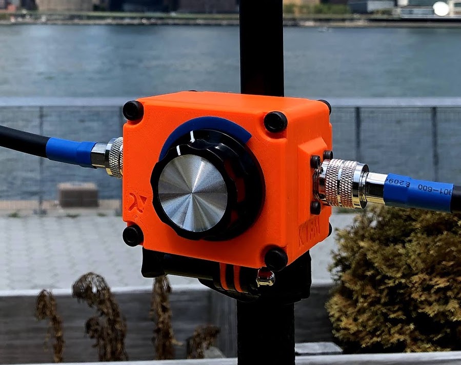
Fully 3D printed, capacitor enclosure
The new enclosure requires no rework in order to be mounted. It is now quickly detachable by using the same mount type as the radiator/exciter assembly. This makes the antenna even more portable and, at the same time, opens the possibility of using other support types in place of the selfie-stick (fishing rods, PVC pipes etc.). The capacitor uses a 3:1 planar reduction that, combined with the a fairly large knob, makes tuning quick and easy. A 3D printed indicator (blue) shows the current shaft position: just by looking at enclosure you can tell where about you are currently tuned and act accordingly when it’s time to tune again.
Exciter loop splitter
Thanks to a new splitter design, the exciter loop is now conveniently made out of a standard LMR240 BNC-male to BNC-male pigtail. The splitter also allows the possibility of using multiple radiator/exciter assemblies in order to, for example, work 6 meters.
Radiator loop mount
I also redesigned the radiator mount to follow the different bending radiuses of the radiator and the exciter loops. Both cables now snap-in with just the right amount of force, therefore zip-ties are no longer needed.
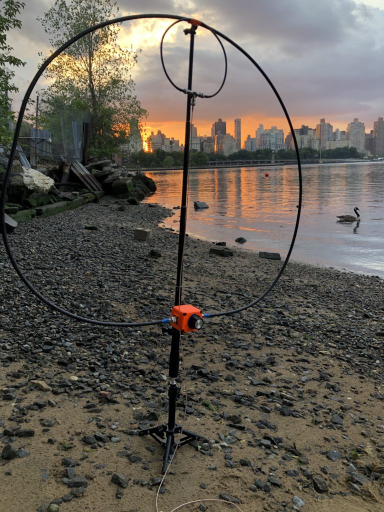
The new loop looks great and works better! I’ve decided to call it K1FM-Loop. If you want to build your own, here are the instructions to do that
After my QRP/Portable QSO with a Japanese station, I was contacted by Hiroshi JL1KLK who asked if he could mention my post in his blog. I obviously consented. In his post Hiroshi shows the similarities between his QRP operations and mine: we both have glasses, we both wear caps, we both are middle aged, we both operate near the water, we both operated standing. There was, however, a difference that stood out: I use an MLA, while he uses a vertical antenna called GAWANT.
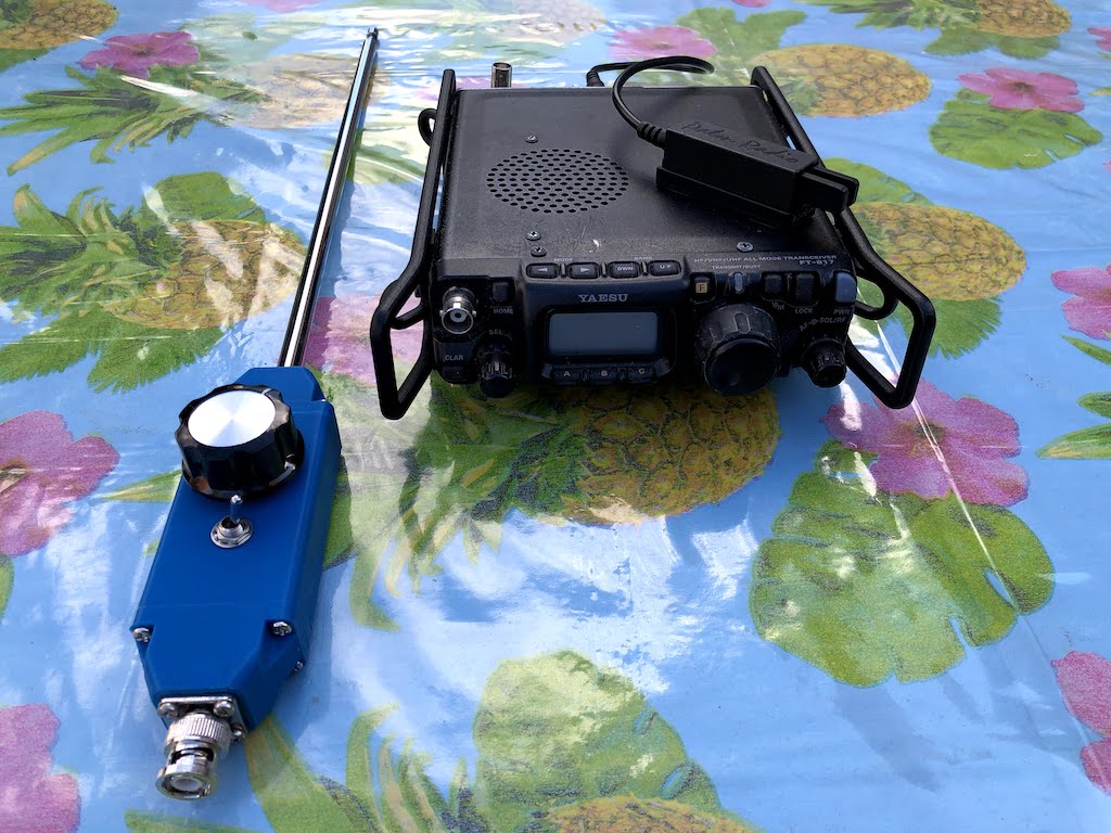
Since I always desired a portable vertical I decided to look into it and eventually build my own. But what is the GAWANT? After some research, I found that it is design somewhat popular in Japan. Technically, it is an half-wave vertical end-fed in a FT817-friendly package. After asking, Hiroshi very kindly provided me all the details with this wonderful document:
Click for more info
In it, I discovered that the original designer, Ariga JF1QHZ, named it after his native Shinagawa-shuku neighborhood. I already had everything I needed to build it, except of course for the 2 meter long telescopic rod and the case. The former was acquired at buddypole.com for $8.50 and the latter was designed and 3D printed by myself. You can check it out at Thingiverse, if you wish.
The GAWANT is ofter used directly on the front BNC of the FT817. I find this impractical because the rod will come uncomfortably close to the operator’s head, and also because the leverage force expressed on the connector appears to be too much. I prefer attaching it to the rear SO239 connector, by means of a right-angle PL259 to BNC connector. I am not excluding the idea of redesigning the case in order to address this particular usability aspect.
The first test of the antenna was in my backyard (these days it might be better to stay home…) and the results were encouraging: in just a few minutes during the WPX CW contest I made 3 contacts: Texas, Europe and Africa. Not too bad!
Here are some more pictures:
Will I switch from using Magnetic Loops to Vertical end feds during my operable operations? Probably not, still the GAWANT is a very nice – super portable – HF antenna that I now have available. Given the cost of making it (I estimate less than $20) I think everyone should build one!
Many thanks to Hiroshi-san for providing all the information, and to Ariga-san for the design!