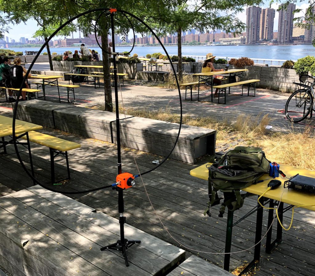
The latest version of the K1FM-Loop is electrically similar to the previous one, but it is designed around off-the-shelf parts or, more generically, items you can readily order online.
This antenna relies – heavily – on 3D printing. Acquiring the non-printed parts and assembling them should be fast and easy as no reworking at all is necessary. The needed tools are screwdrivers, wrench keys and a soldering iron. You also need a 3D printer, of course, or at least access to one.
Lets’s start from the parts list:
- 3D Printed parts
- Exciter Loop Splitter PCB (available shielded or unshielded – see below)
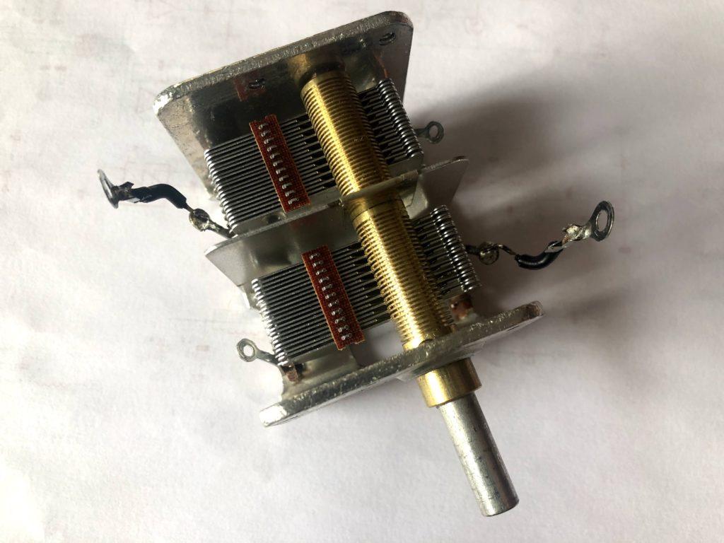
- Variable Capacitor – Oren Elliot Products P/N S2-332x2P (21 blades, 2 gangs of 9.3 – 332.4 pF used in series)
- ~40 inch selfie-stick
- gopro bike mount
- 15 inch photographic tripod
- PL259 to PL259 LMR400 cable 125 inch long (for the radiator loop)
- BNC-male straight to BNC-male straight LMR240 cable 25 inch long (for the exciter loop)
- BNC-male straight to BNC-male straight RG316 cable ~6 ft long (for the feed line)
- BNC-female Molex P/N 0731000105 (3 pieces for the Exciter Loop splitter)
- SO239 panel connector (2 pieces for the capacitor enclosure)
- MF-A05 Knob, 1/4inch shaft
- Socket Head Cap Screw, M5-0.8mm Thread, 12mm Long, Alloy Steel, Black Oxide (8 pieces)
- Button Head Socket Cap Screws, 6-32 x 5/16″, Black Oxide Alloy Steel (3 pieces)
- Hex Socket Head Cap Screws Bolts, M3-0.5mm, 9mm Long, Alloy Steel , Black Oxide (8 pieces)
- Hex Self Clinching Nuts, M3-0.5mm (8 pieces)
- 18AWG electric cable ~5 inch
- M3 Ring Cable Lugs Terminals (4 pieces)
The antenna is composed of three parts that I am going to describe separately. They are:
- Capacitor assembly
- Radiator / Exciter assembly
- Supporting structure
Let’s see them one by one:
Capacitor assembly
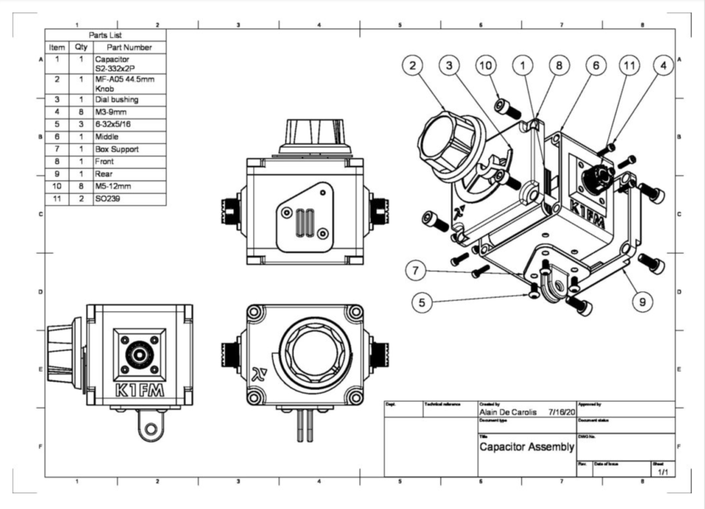
First of all, you need to print the necessary 3D printed parts. It might be opportune to print the Dial Bushing in a different color, in order to make more visible against the rest of the box.
I printed the box in PETG because of the enhanced mechanical and thermal characteristics. ABS would also be opportune I think, or even PLA (provided you are careful not to leave it inside of a burning car).
As the print goes, you can start working on the other parts.
All you need to do is solder a piece of cable on each gang terminal, on opposite sides. Terminate the cable extensions with a ring contact, like so:
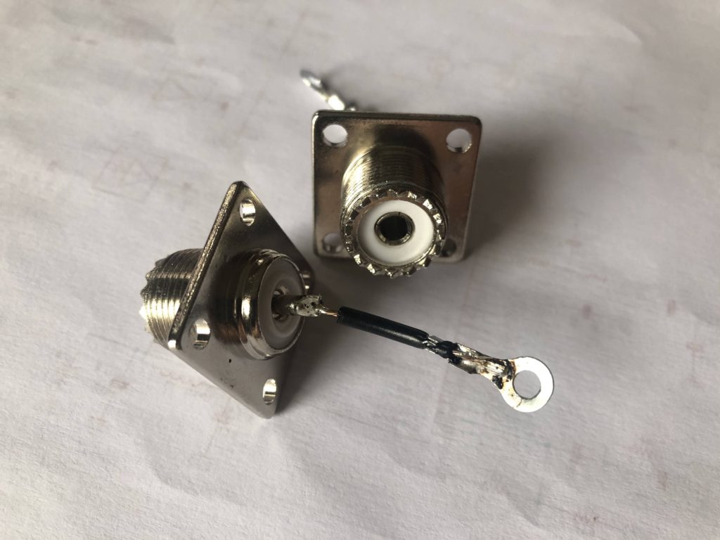
Optionally, you could solder the same extension on the center connector of each SO239. This will allows to use the center conductor as part of the radiator (Do I think this is useful? I don’t, but I’m going to do it to avoid the complaints). Here are the connectors, ready to be used:
Now you can begin assembling the box.