Radiator / Exciter assembly
The exciter loop consists of a 25 inch long LMR240 piece that closes the feed line between the center conductor and the braid. In my solution I use a center PCB piece with 3 BNC connectors that make it possible to quickly disconnect the feed line and eventually (whenever needed) replace the exciter with a different one.
I have two version of the PCB: one that is unshielded (the classic one) and another that is instead shielded (a faraday loop).
According to some, the shielded version is slightly superior in terms of noise and SWR (the noise claim is practically unsubstantiated, while the SWR marginal). In any event, for years I always have been using unshielded exciters with great success. This time, however, I decided to provide an option for a shielded exciter as well. I still haven’t had a chance to form an opinion about the effective superiority of either solution, so the choice is up to you.
All you need to do to make your own coupler is order a PCB (either shielded or unshielded) and the three Molex Connectors. Solder them together, attach your cable and you are ready to go.
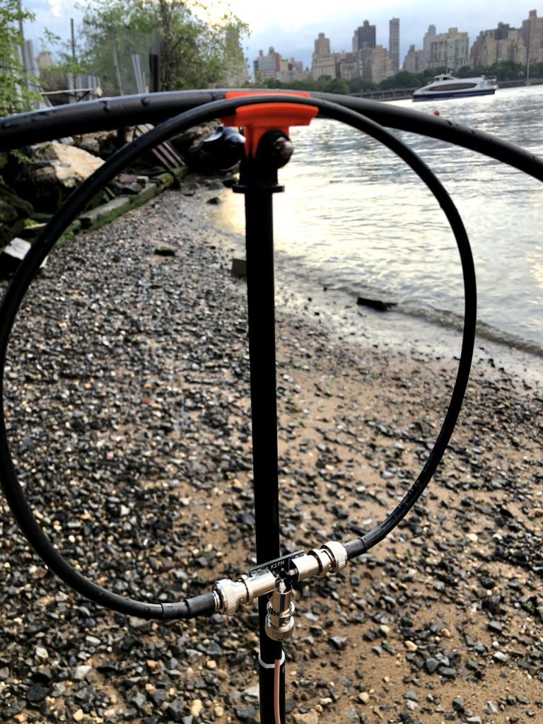
Use the Coax Support part to mount the radiator in the middle of the radiator loop. During transportation I like to keep them together with a double SO239 connector:

For the feed line I like to use 6ft of RG316 because its light and flexible. Others prefer RG58.
The radiator/exciter are done. Let’s not examine the supporting structure: