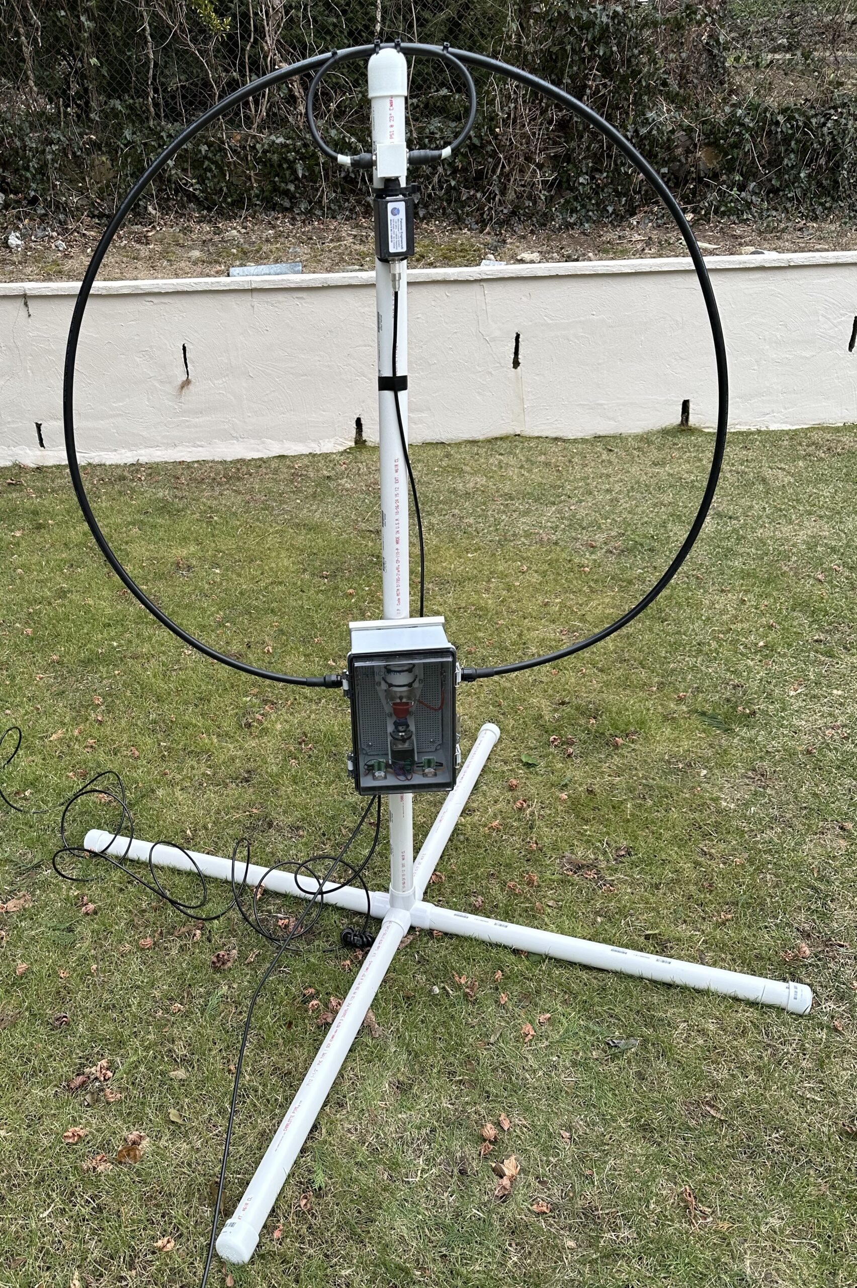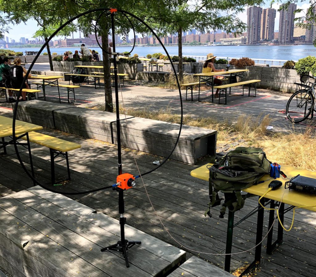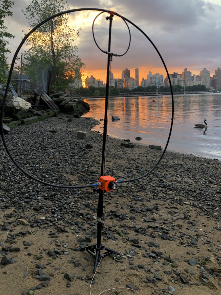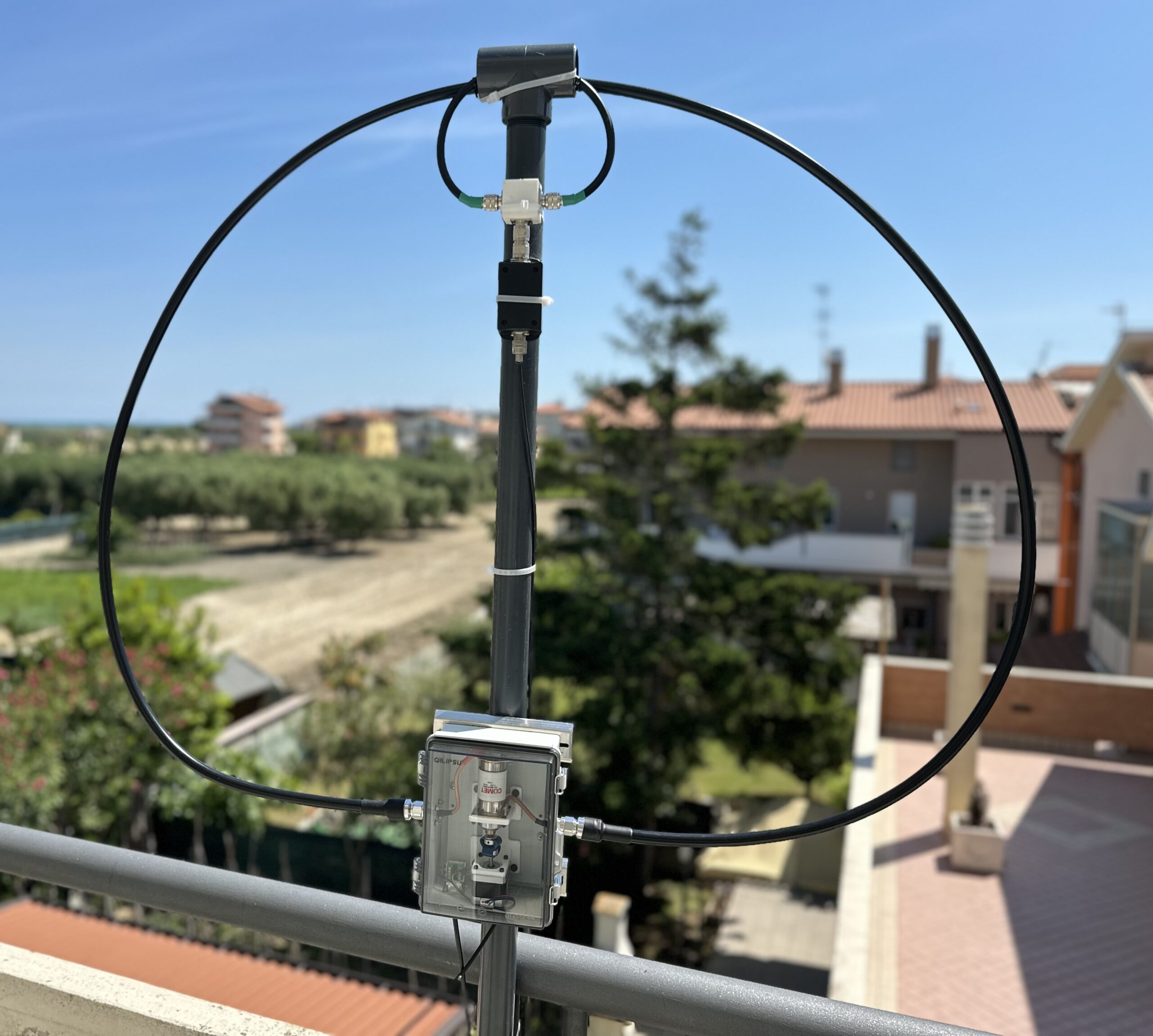
I knew I was going to spend some time in Italy so, for the occasion, I decided to design another QRO loop to be installed permanently over there. I’m calling it the IZ6 Loop.
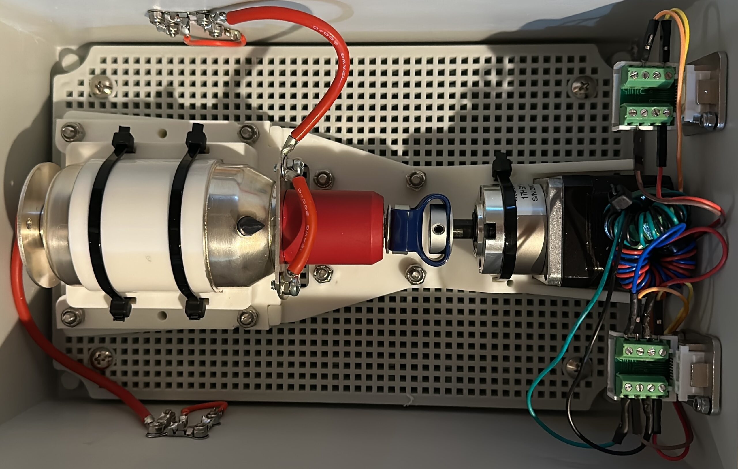
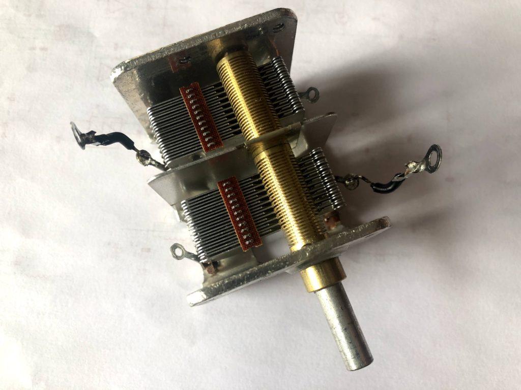
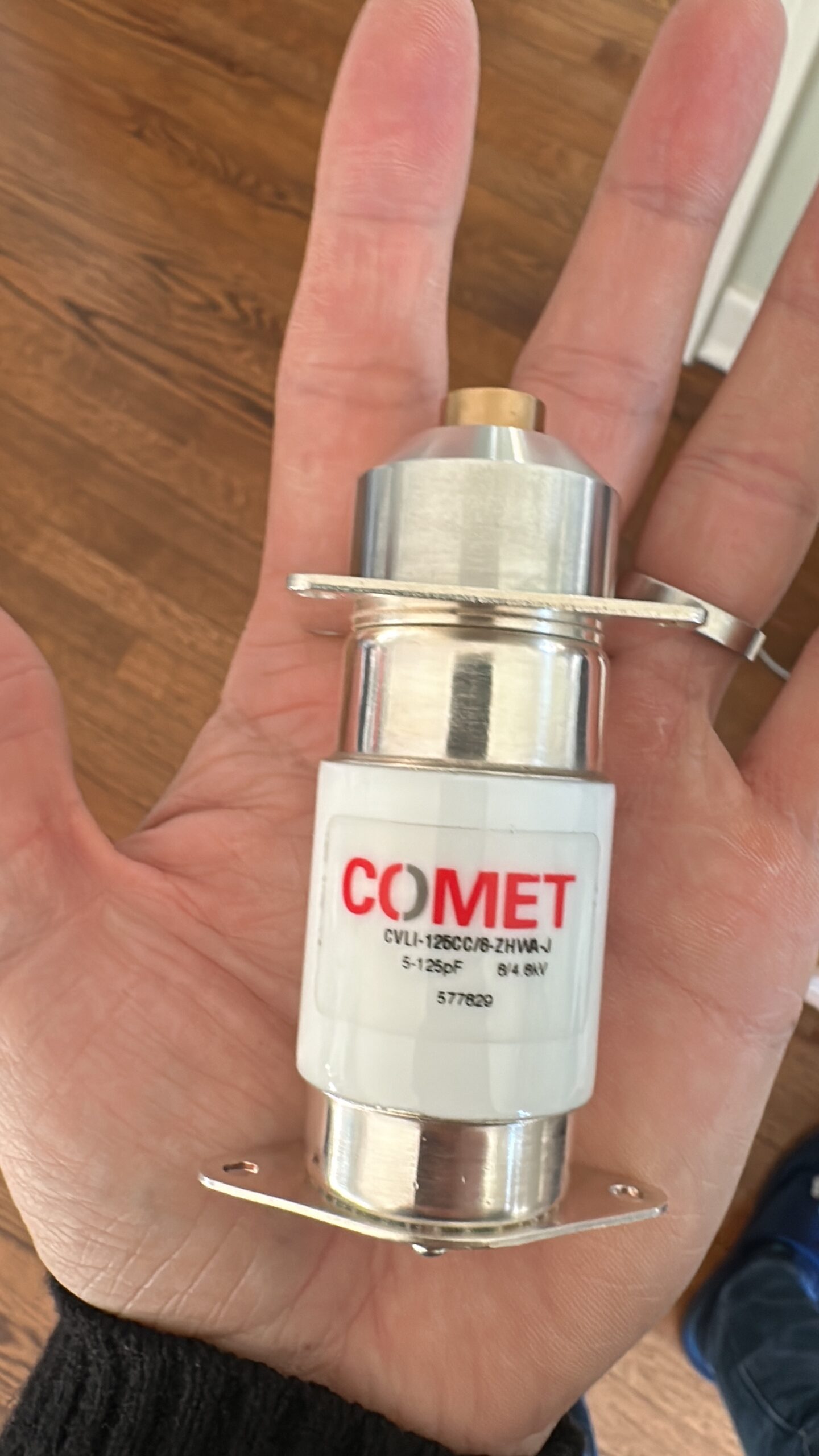
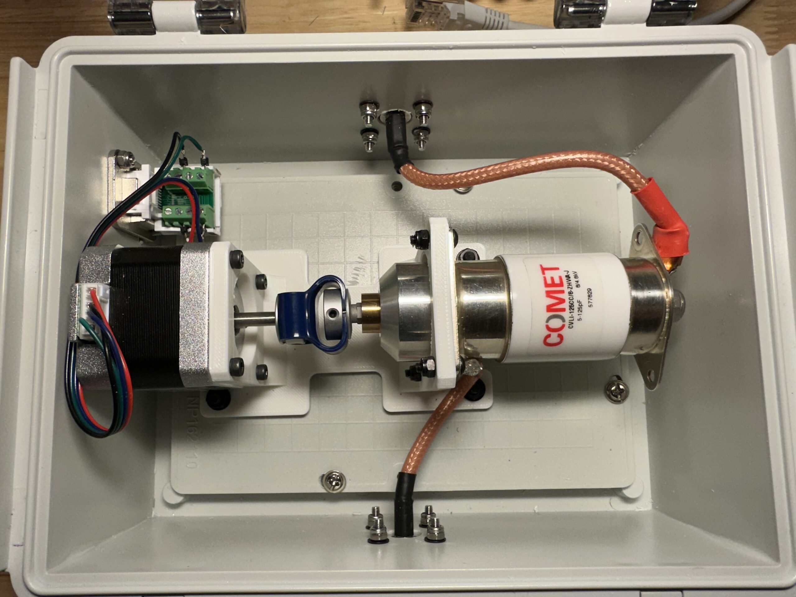
This time I decided to use a smaller capacitor so I selected a Comet CVLI-125CC/8 which does 5-125pF and peaks at 8kV (I got it from Ebay for $149).
The reason for a smaller capacitor is I realized that going above 150pF is generally counterproductive: on the low bands performance isn’t going to be good and – at the same time – the extended tunable range will require micro-stepping and/or gear reductions. The low bands demand a separate, multi-turn (or larger) magnetic loop which would still require less than 150pF.
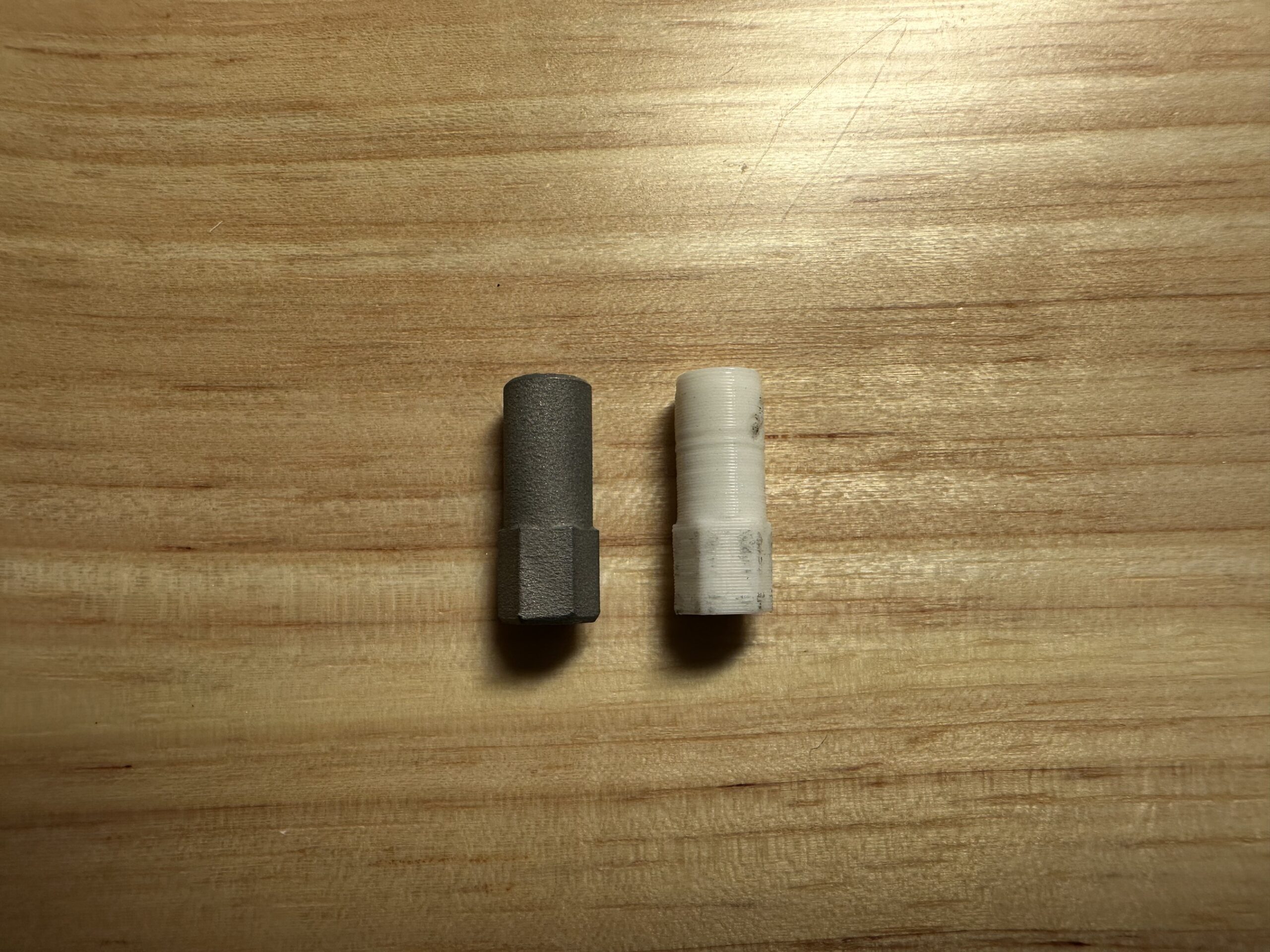
This particular capacitor doesn’t come with a pre-made shaft so I had to draw one. First I printed it in plastic then I decided to have it manufactured in aluminum for an extra $10.
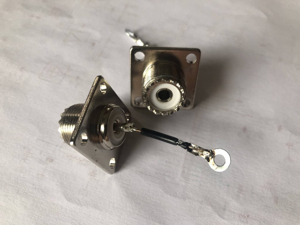
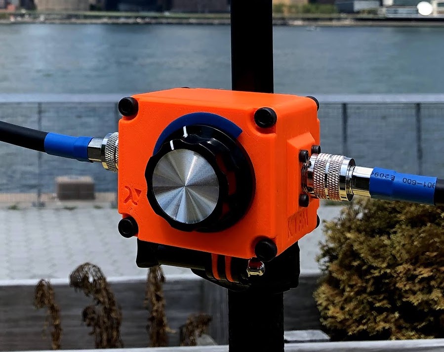
The enclosure I used is of the same kind I used on my other loop, but a bit smaller in size. I’m still using N connectors for the radiator disconnects and ethernet for the control wires. The stepper motor is a simple 38mm NEMA 17. Because of the small capacitor size, no micro-stepping nor gears are needed. I also tried using a 23mm stepper but that size worked unreliably due to lack of adequate torque.
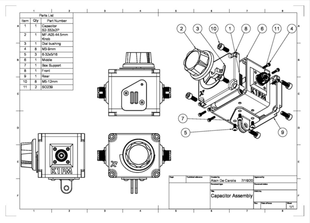
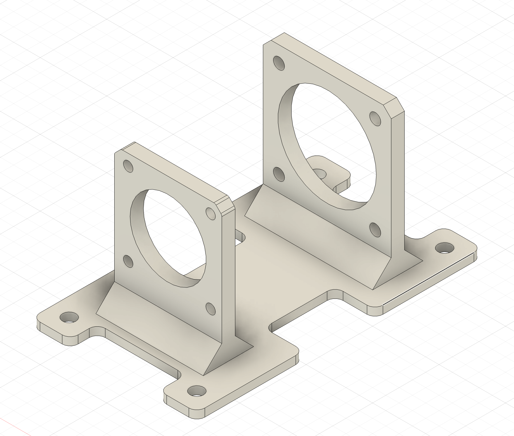
I have designed a simple support to hold the capacitor and the stepper in axis. The support can be printed on most 3D printers and on a large variery of materials without supports.
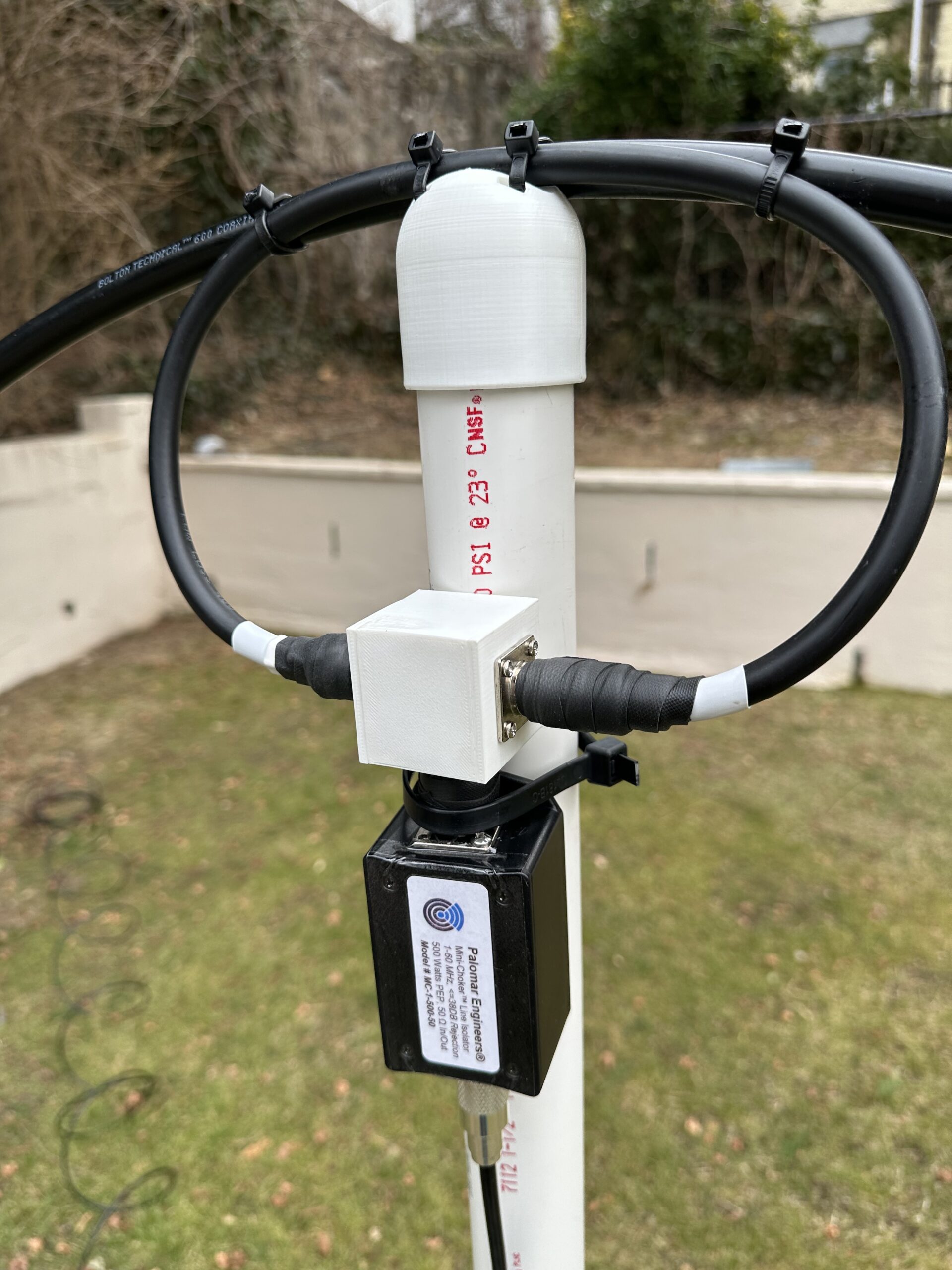
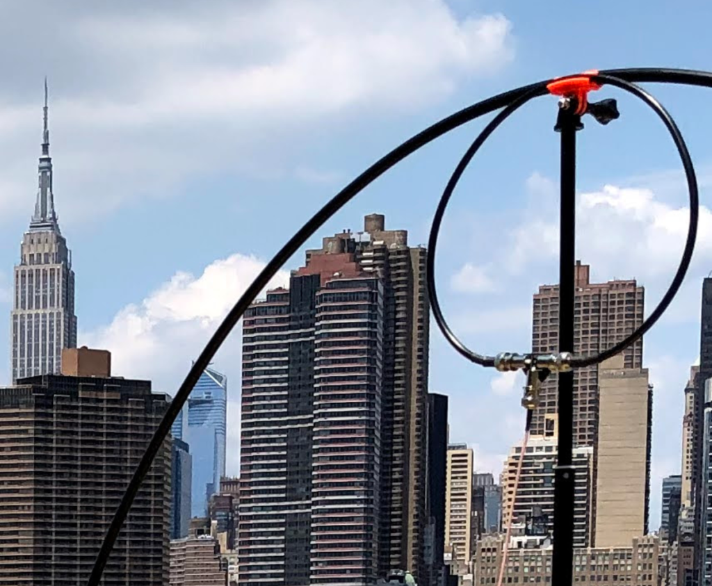
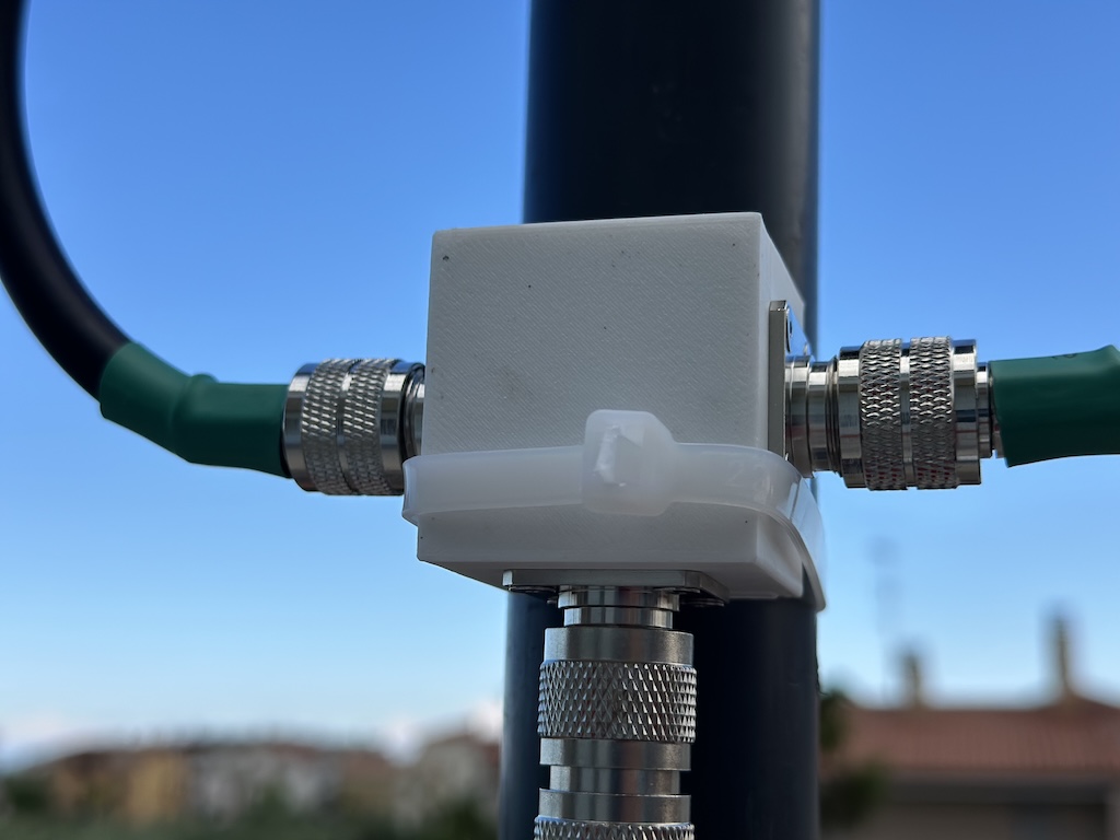
The exciter loop is made using the quick and dirty splitter I recycled from my last project. This part could be better but, hey, I have a much larger family now (and a lot less time).
Radiator is made with 10ft of LMR600 coaxial cable and resonates between 7.4 to around 30 MHz (a slightly longer radiator could also cover 40 meters but performance would be poor).
The rest are standard bolts, washers and nuts. Add a cheap controller, some spare time, a lot of patience and there you go: for less than $300 you have a fully featured, vacation ready QRO magnetic loop.
Results are quite good. So much so that I am planning to install it permanently on the roof, probably with a rotor.
These are the main parts I used:
- Capacitor Comet CVLI-125CC/8 ($149)
- Stepper Motor NEMA 17 38mm ($6)
- Enclosure QILIPSU UL94-V0 Outdoor Electrical Box 8.3″x6.3″x3.9″ ($26)
- Pole Mount QILIPSU Pole Mounting Kits, 304 Stainless 175x48mm ($14)
- Ethernet connector PENGLIN 2PCS RJ45 Panel Mount Screw Terminal Adapter ($10)
- Capacitor/Stepper Support and Loop Splitter (printed in house +$10 for metal shaft)
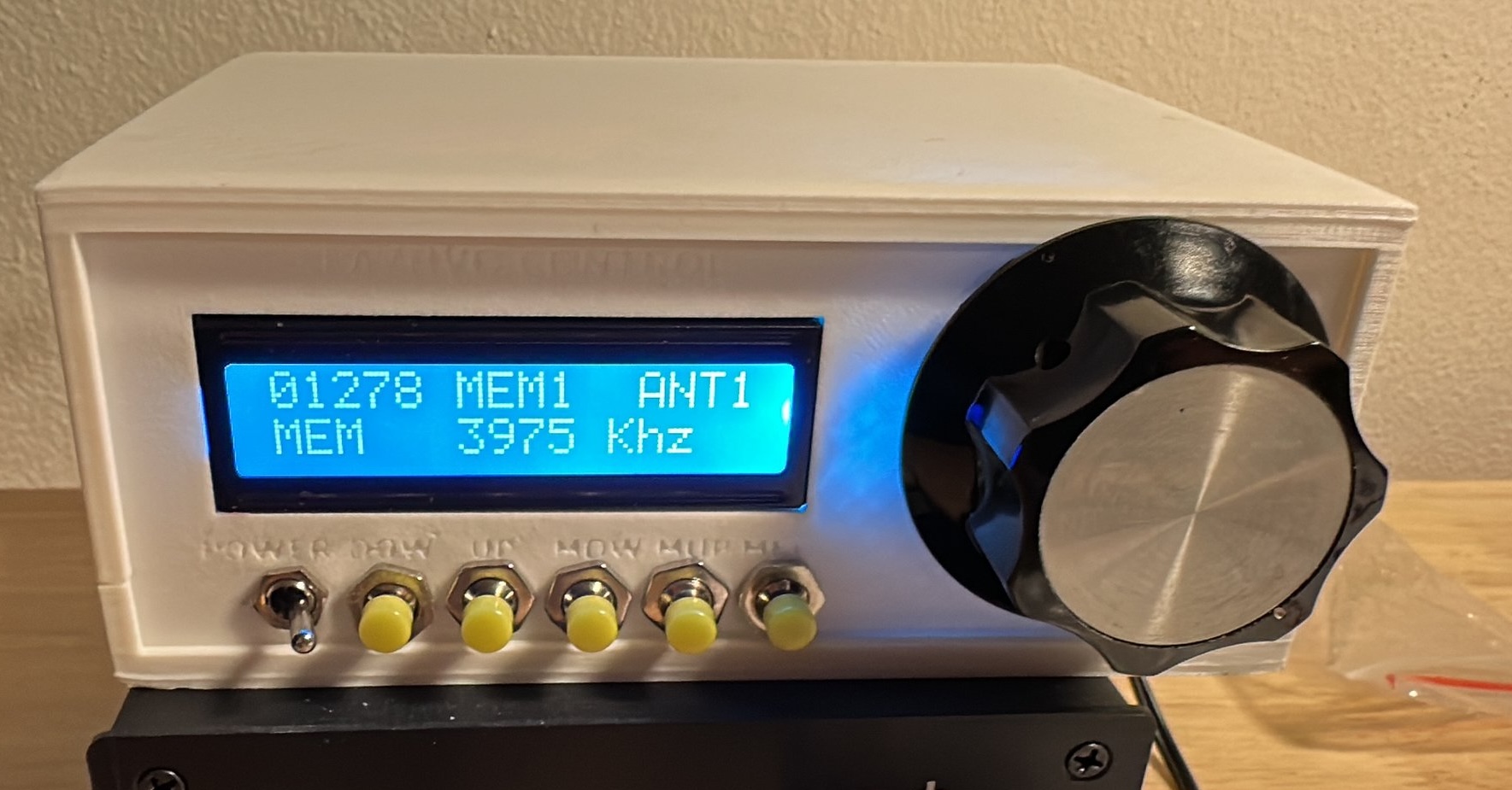
- Loop Controller (EA7VHO or K1FM)