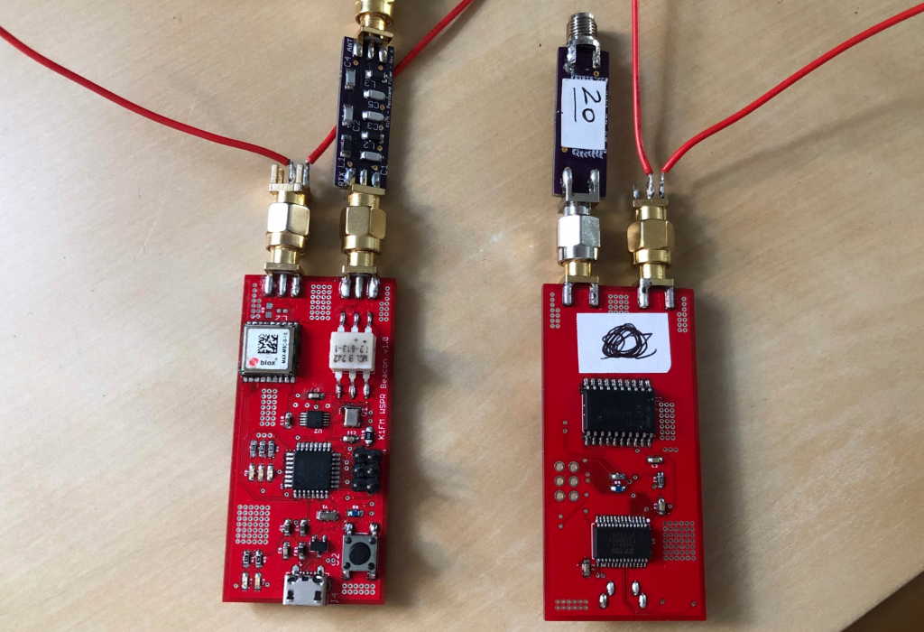
I recently built a couple of identical WSPR transmitters to be used in direct comparisons between magnetic loops and other antennas, or even between various kinds of magnetic loops. They are now available on Github.
The transmitters are based upon the Si5351 clock generator and their RF section was inspired by the excellent Zachtec’s products. An onboard GPS receiver is used to automatically provide timing and location. In the absence of a GPS fix a button can be used to start transmitting. The same button can also be used to cycle between 5 predefined WSPR frequencies. There are no onboard filters therefore external filters must be used in order to maintain compliance with FCC rules. SMA connectors provide connectivity for both the HF and the GPS antennas.
The firmware is based upon existing libraries and was created around version 1.0 of the board. Version 1.1 introduces an important extra feature: auto-calibration.
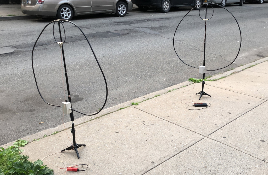
I also built another magnetic loop, identical to the one I already have. Together, they will serve as a testbed for my comparison tests.
I still have my Italian callsign active. During my short holiday in Central Italy, I took the opportunity to use it again. Here I am at the beach doing some QRP contacts (in the video, R9MM):
I really like going QRP from a not so popular location on East River, right between Manhattan and Queens. I normally don’t plan for it. I just go whenever I feel like it and, obviously, I have time to do that.
Yesterday was one of such occasions. It was a particularly interesting day because the WPX CW Contest was going to start at 8PM local time and I had come home relatively early from work.
I wasn’t planning to try to contact CW stations at the very beginning of the contest (too late for me to stay at the river, bands too crowded). Instead, the idea was trying to catch those operators warming up their amplifiers (and their fingers!) in the hours immediately preceding the start of the competition.
Sure enough, those stations were exactly there, as I expected them to be. In one hour I made 9 contacts, all Europeans (plus Russia). Another fun day at the river! Here is the video:
The Pico Balloon concept is simple: you build a transmitter small enough to be carried around by one or two common party balloons. As the transmitter floats around the globe it transmits its current position and altitude so you can follow its path in realtime. If you do it right, the balloon will circumnavigate the globe… repeatedly. Great stuff! I had to do it.
After realizing that it was relatively easy to construct a WSPR beacon based on Arduino and a clock generator, a few months back I decided to try building one.
The first attempt was on a breadboard with an Arduino Pro Mini, a uBlox breakout board and the Etherkit s5351a breakout board. After writing a few hacky lines of code (WSPR libraries are already available) WSPR worked! All I needed was making everything small enough to be carried by a party balloon.
I decided I was not going to use the standard Arduino Pro Mini. Rather, I was going to load the Arduino boot loader on a ATM328P myself and have everything else (GPS + Clock Generator) on a the same board. This unit also worked and, technically, was already small enough to be carried around by a couple of large balloons.
But how was I going to power it? Was a small LiPo battery suitable? After checking the specs I realized that even the smallest ones were too heavy. On top of that, batteries don’t take extremely low temperatures well so it definitely had to be solar power.
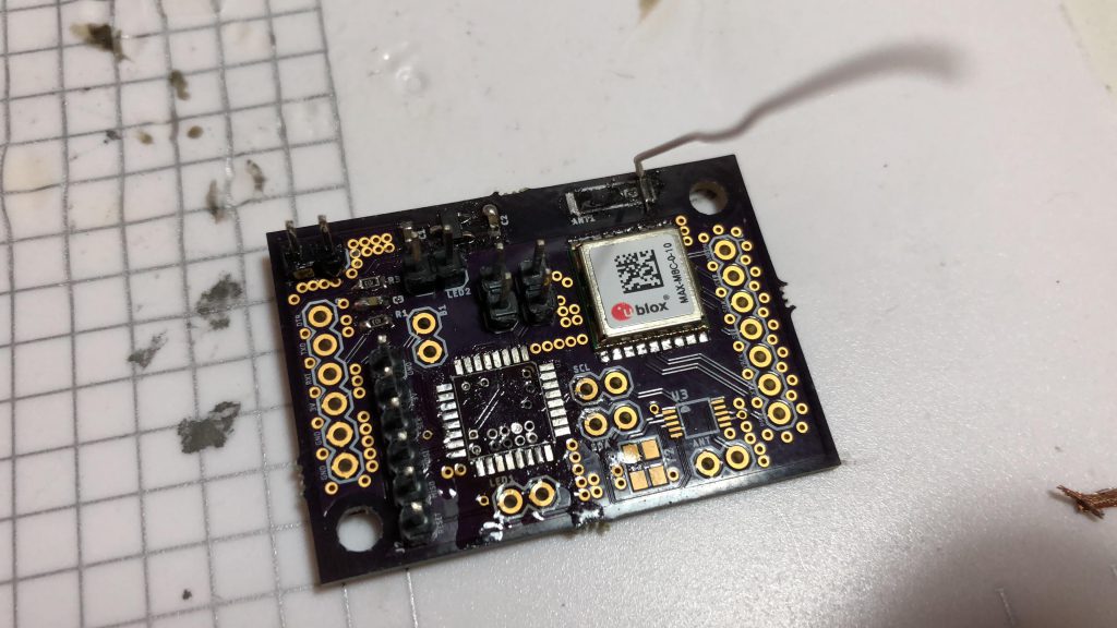
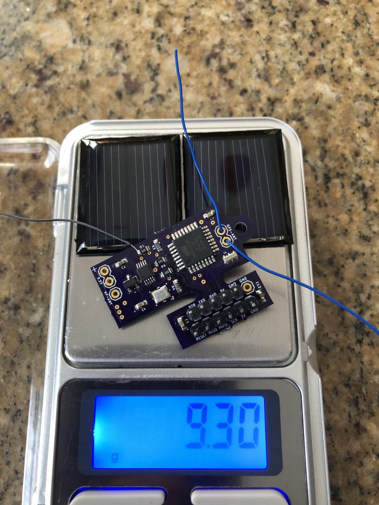
In the next revision, which I called 1.1, is where I faced the first serious obstacle. Until that point I was able to successfully load the Arduino boot loader without too much trouble using an ancient Arduino Uno as the ISP programmer. For reasons I still can’t understand, that wasn’t the case anymore with revision 1.1. Fortunately, when I was close to giving up, I remembered that back in the days I had purchased a proper ISP board and tried with that: Bingo! Problem solved. As you can see, on version 1.1 all necessary programming connections have been moved to a section of the PCB which is supposed to be cut out before launch (the wires soldered on the side were part of my desperate attempts to troubleshoot the ISP malfunction…).
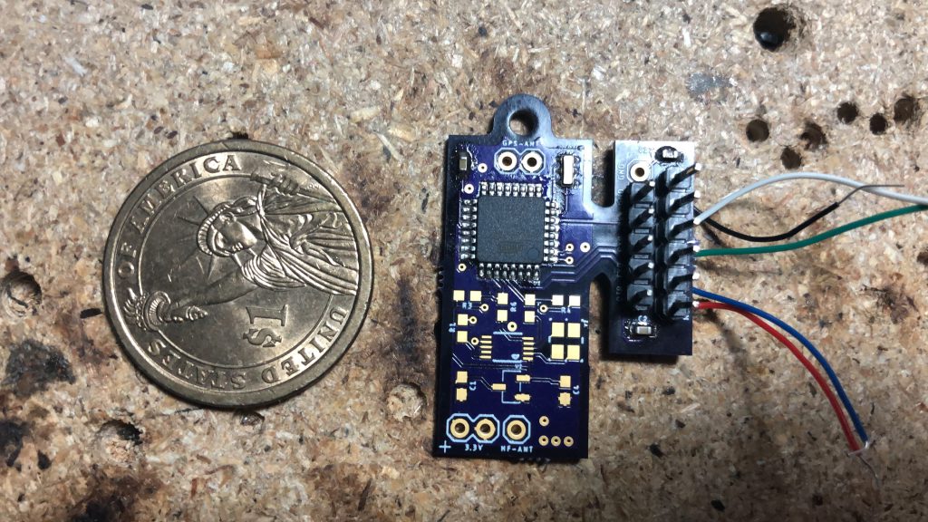
At this point I had a transmitter that – together with the solar panels – weighted less than 10 grams! I really believed it was just about time to buy the balloons when I faced the second problem: I had grossly overestimated how much power solar cells can deliver. Yes, tensions can be pretty high but currents… well, currents are tiny: there is absolutely no way the beacon can be carried around by small balloons while being directly powered from solar panels as I originally envisioned. I needed something light that charged a capacitor and then – only then – I could start transmitting.
By searching things like “Tiny Solar Power Charger” I ended up on Jared’s (N7SMI) page. I was stunned: his pico balloon concept and hardware was identical to mine except that he completed it years in advance and, unlike mine, his actually worked and flew already many times. Jared had already solved the power issue with a 1.5F super capacitor charged by an SPV1040 controller and two 0.5V solar cells. Brilliant! Not only that. In order to save power, he provisioned his transmitter to selectively switch off the GPS and/or the clock generator. He also has a temperature sensor and – surprise surprise – a CW beacon too! Clearly, I now have enough material for version 1.2.
On part two I will publish my current schematics, PCBs and source code.
After describing my mini loops (here and here), this time I am going to write about the classic “full size” version that I have been using for a while.
At Dayton the Hamvention of 2018 I took my loop with me and I mounted it on a PVC support that fitted a military style backpack. It made quite a splash! Eventually, someone took a picture that ended up on the August 2018 QST and the 2019 ARRL Calendar front-covers. That’s when I proposed the QST editors an article which described how to make the antenna. QST accepted but took its time, finally publishing the article with the May 2019 edition.
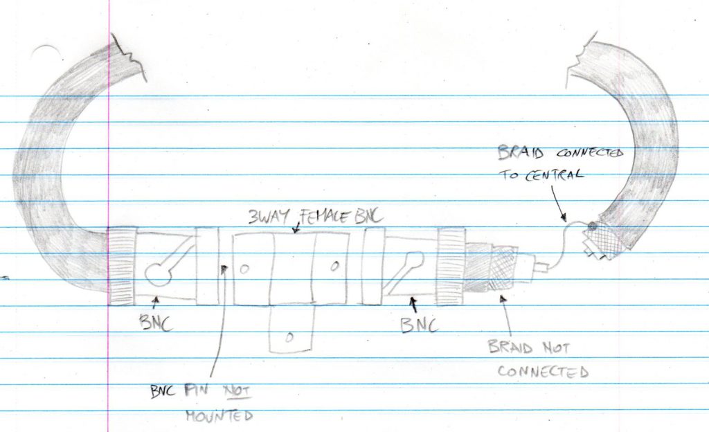
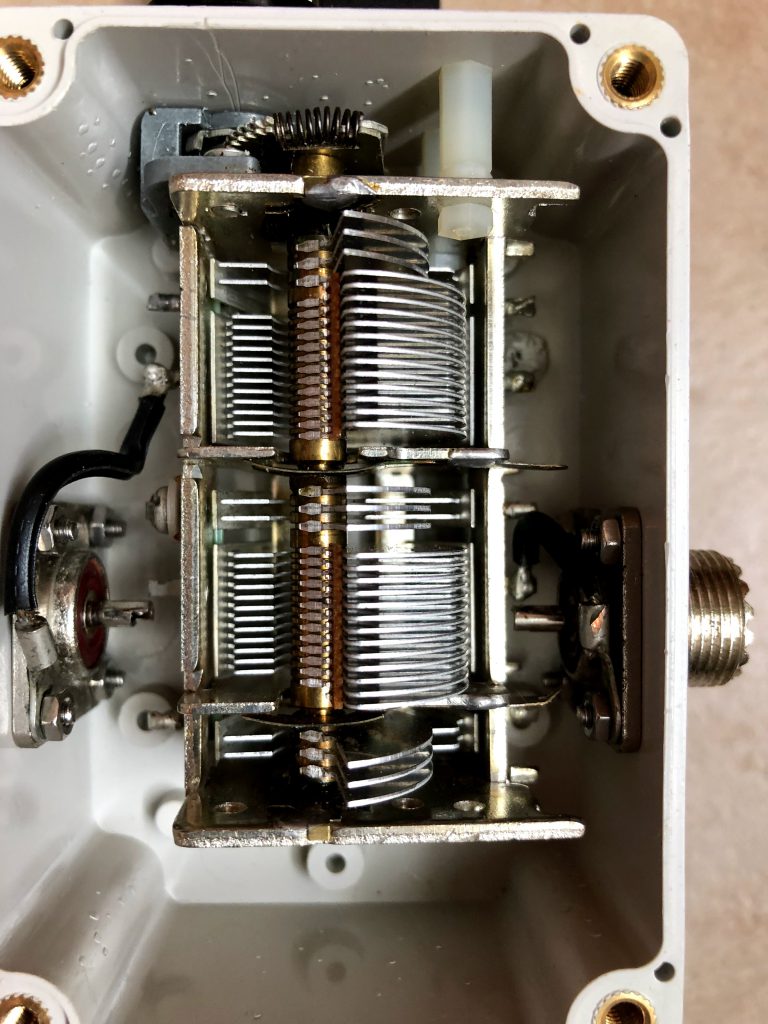
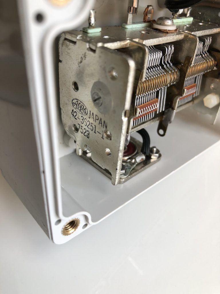
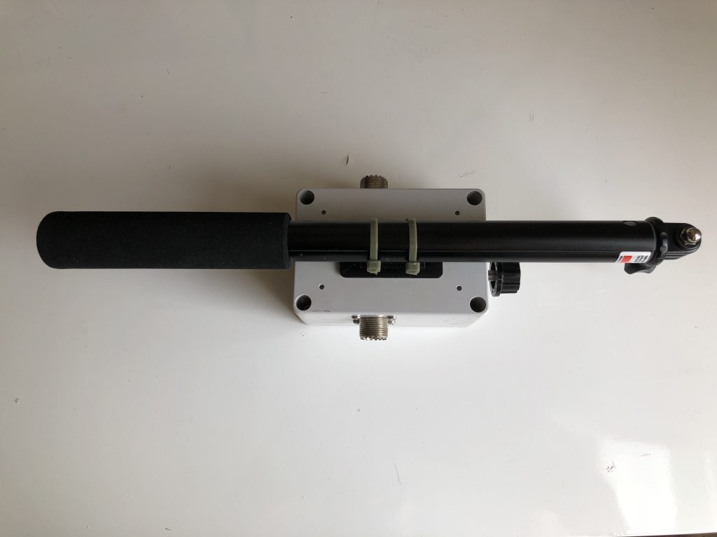
The K1FM Loop consists of a LMR400 radiator (124″) fed by an LMR240 exciter (25″). The radiator loop is terminated by a geared, multi-stator variable capacitor made by Alps (14pF to 165pF, P/N 42-36251-1). The exciter, instead, is constructed to be terminated by a 3way BNC adapter. The geared capacitor and the loop configuration have been inspired by the AlexLoop while the exciter construction and the selfie stick by Alpha Loop.
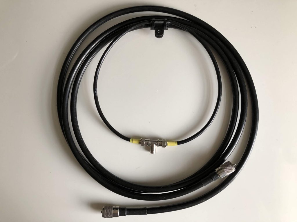
Radiator – Exciter Loops assembly
The exciter loop takes a bit of patience in order to be manufactured this way. Quite a bit, actually. Of course more classic approaches can be used as long as the overall size remains the same. Both loops are mounted on the selfie stick using a custom 3D printed bracket that fits on standard camera mounts.
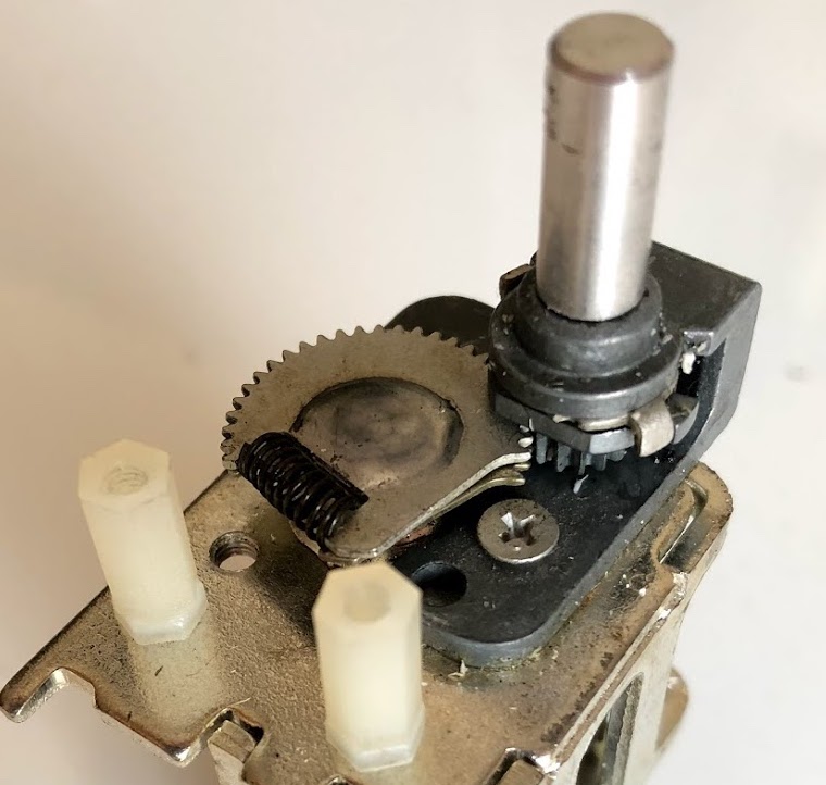
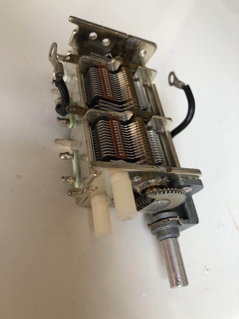
Capacitor with mounted nylon standoffs
Variable capacitor, ready to be mounted
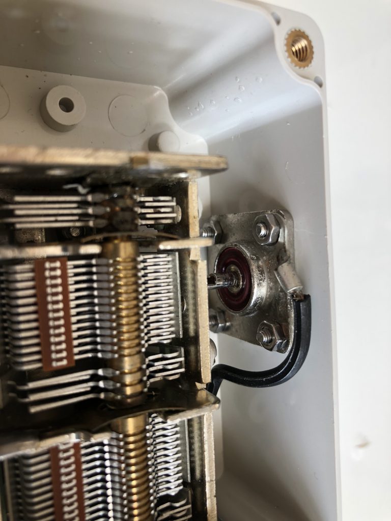
Capacitor connection detail
Capacitor P/N
The other critical aspect of this project is obviously the capacitor. It is the capacitor which defines the bands you can use, the resolution you get (how “touchy” the loop will be…) and – last but not least – how much power the loop will be able to handle. The 15-165pF geared type is some kind of a sweet spot, a very good compromise for a loop this size when used QRP. Unfortunately Alps no longer makes this capacitor but from time to time they pop-up on Ebay for about $20 each. You can, of course, replace this capacitor with equivalent ones (similar, non geared capacitors are more common and much easier to find).
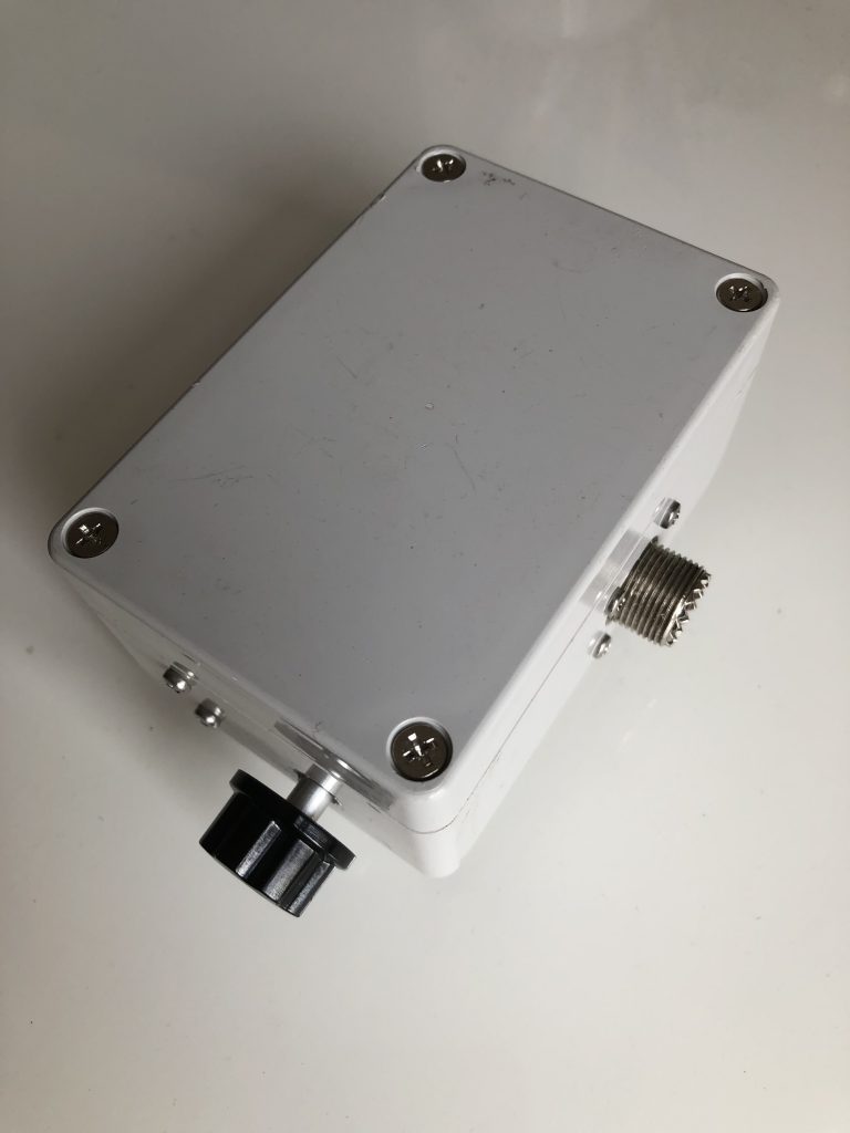
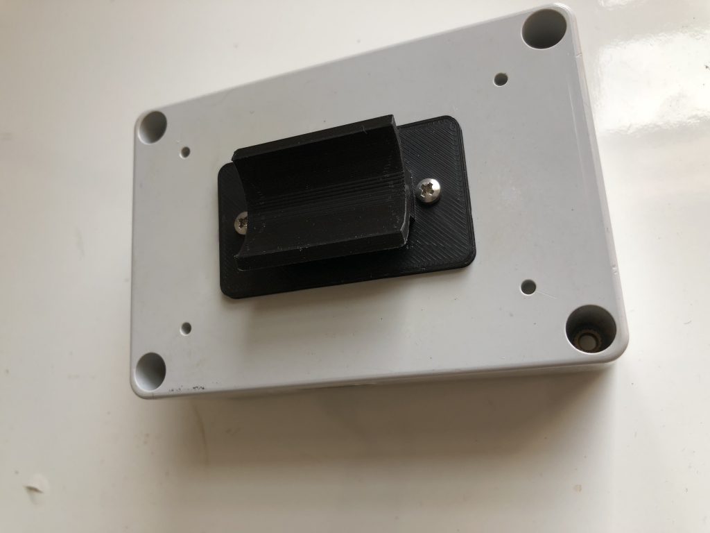
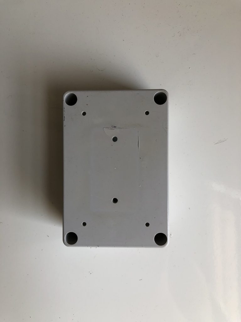
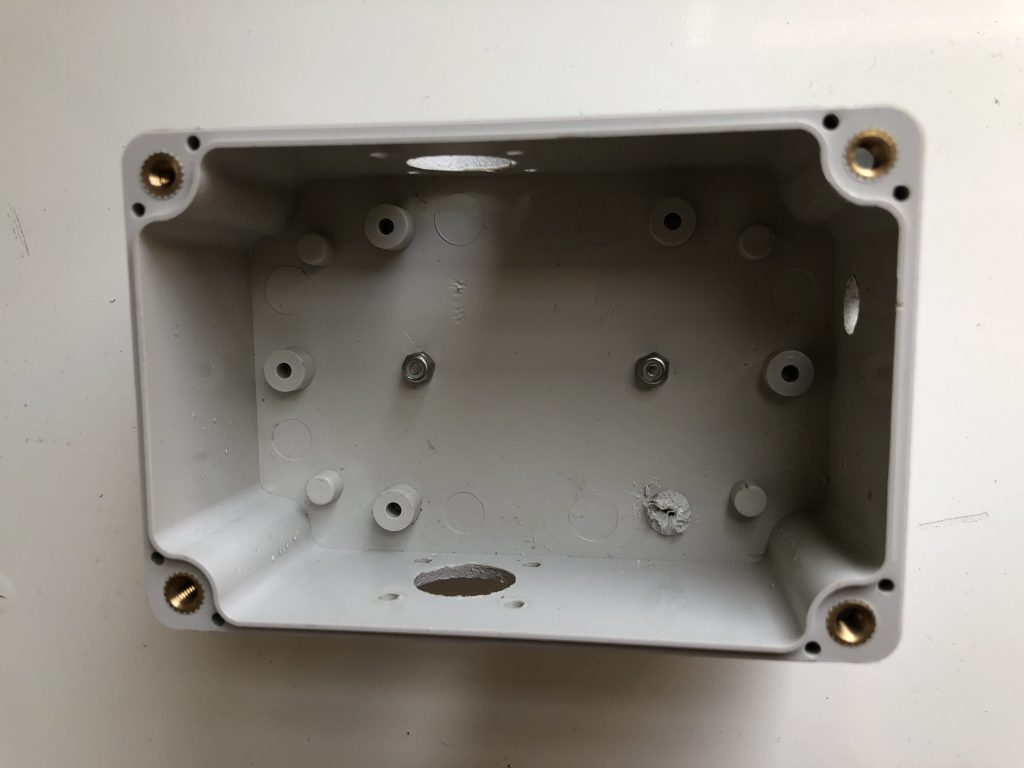
The capacitor enclosure is fundamentally just a box that holds the capacitor against the selfie stick, connecting it to the radiator loop. The box I used is made by uxcell and measures 3.9″ by 2.6″ by 2″. I mount it against the stick using a custom 3D printed ABS bracket.
The list of all necessary materials, from the main loop to the last nylon screw, is here. Overall the cost for a single antenna should be around $60 but the final cost will vary depending on how much you will spend for the capacitor and for the 3D prints.
Performance of magnetic loops this size have been extensively analyzed and reviewed. Mine is no different than the others. Please do not expect miracles! Ultra-Portable QRP is hard stuff and you will need to rely the 3 P’s: Propagation, Perseverance, Patience. In a nutshell this loop performs at around the same level of full sized half-wave dipoles or of a vertical antennas. Yet, you are running 5W watts into it therefore plan for the right time, the right band and the right location if you want to work DX on voice. All in all, I find it a bit lacking on 40 and I don’t use it on that band unless it is inevitable. 20 and 30 are very fine and – when conditions permit – so are 17, 15 and 10.
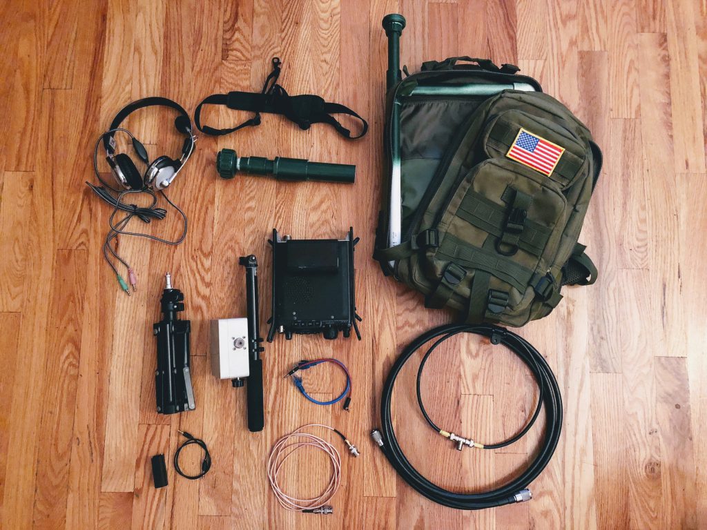
Other than the loop, I normally carry my FT-817, a WinCamp Headset adapter, a PC Headset, a Palm Radio CW Pico Paddle, a mini tripod and a military backpack with a PVC antenna mount. I recently added FT8 and wireless headsets, but that’s going to be detailed in other posts.
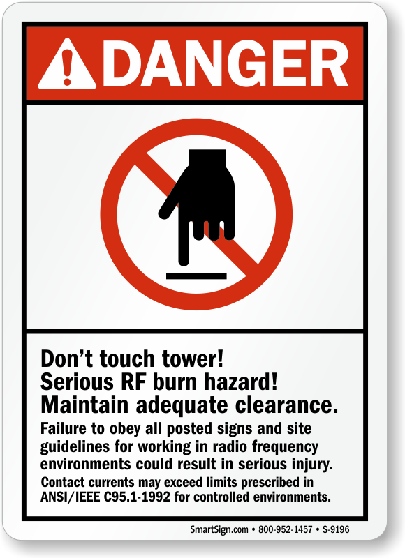
Finally, I’d like to spend two words on RF safety. As a licensed Amateur Radio operator you should already be aware of the following but I, for the sake of safety, I’ll repeat what you probably already know. Loops can be dangerous around people. Do not exceed power! By doing so you would irreparably scar your capacitor. If you really go heavy, you basically built a soldering machine: sparks will fly and fires might start. Moreover, even when QRP, this loop will exceed FCC exposure guidelines when used in close proximity. To be on the safe side, nobody should be closer than 2 meters from this loop, regardless of how much power you are using. Finally, do not touch the radiator while transmitting because you could be burnt, electrocuted or both (~800V at 5W, ~4000V at 100W!).