Categories
HF Portable

K1FM Mini Magnetic Loop 2.0

In the effort of improving my ultra-portable HF antenna setup, I first looked into a Capacitively Coupled Magnetic Loop, better known as the Army Loop (or Patterson Loop). The Army loop performed well. It was so portable that I enjoyed using it before, during and after numerous Tennis matches… Here is one example:

The Army loop, however, sometimes presented a little bit of a challenge because in order to tune you need to operate two capacitors, instead of one. Generally speaking, one capacitor affects resonance while the other affects the coupling impedance. The main problem I found is that even when the SWR is very low, such impedance isn’t always what you would expect it to be (around 50 ohm). You can still match it by operating the second capacitor but there really isn’t a way – while portable – to tell how close you are to the perfect match. That’s the main reason why I decided to look for alternatives.

The idea for my next portable loop came from  the Wonder Loop by Wonder Wand (not to be confused with the ‘G4ILO Wonder Loop’, which is unrelated). Wonder Wand’s Wonder Loop looks like an Army loop, but only has one capacitor. After taking a look inside I was intrigued to see a Toroidal transformer. My first reaction was: WFT?!? Then I remembered seeing something similar on the excellent N4SPP page about loops (probably the best page about magnetic loops actually available). Here is what Frank N4SPP has to say about this coupling method:

N4SPP
N4SPP’s coverage of the toroidal transformer coupling solution

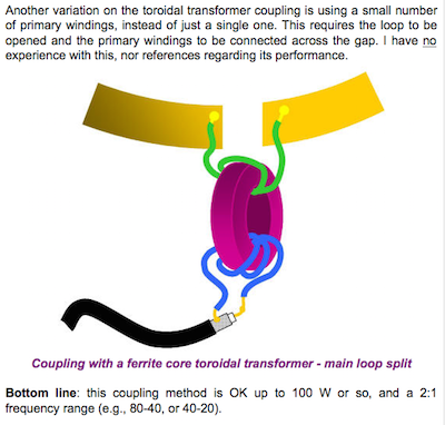
The advantages of such design are two:  no need for a coupler loop and only one capacitor. Precisely what I wanted!
At this point you might ask why don’t  I just use the Wonder Loop. The thing is that the Wonder Loop isn’t simply ultra-portable, it is microscopical. It’s radiator is made of a 1 mm thin copper wire… a bit too much, I guess. All I wanted was the same concept as the Wonder Loop but with a radiator of my choice (and at a smaller price!).

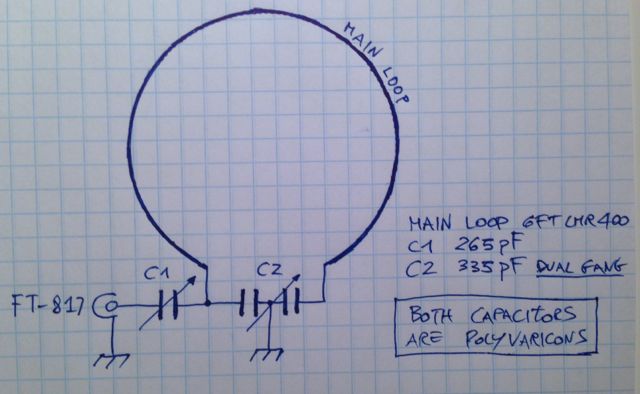
Here is the schematic I started working on:

img019c

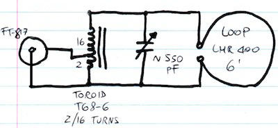
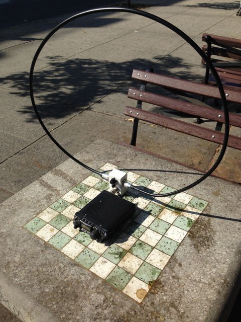
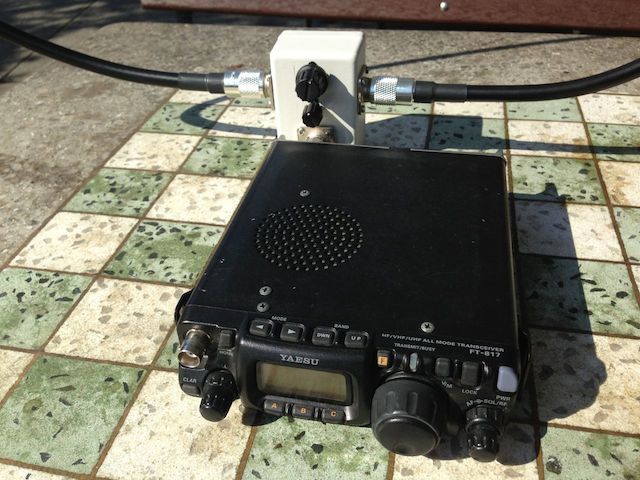
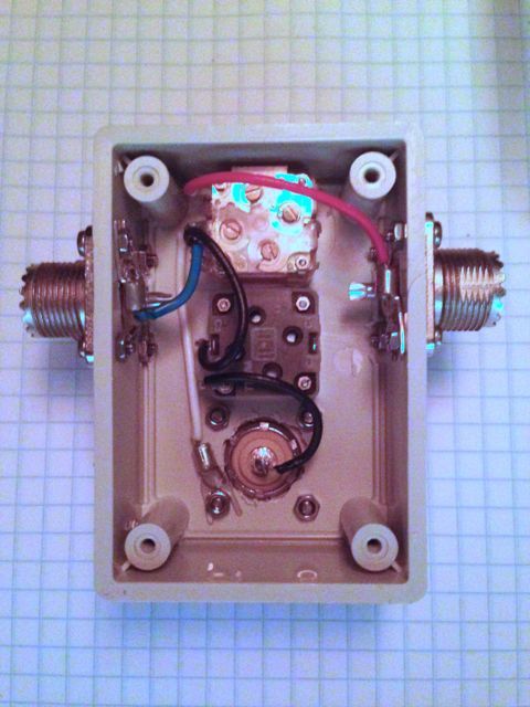
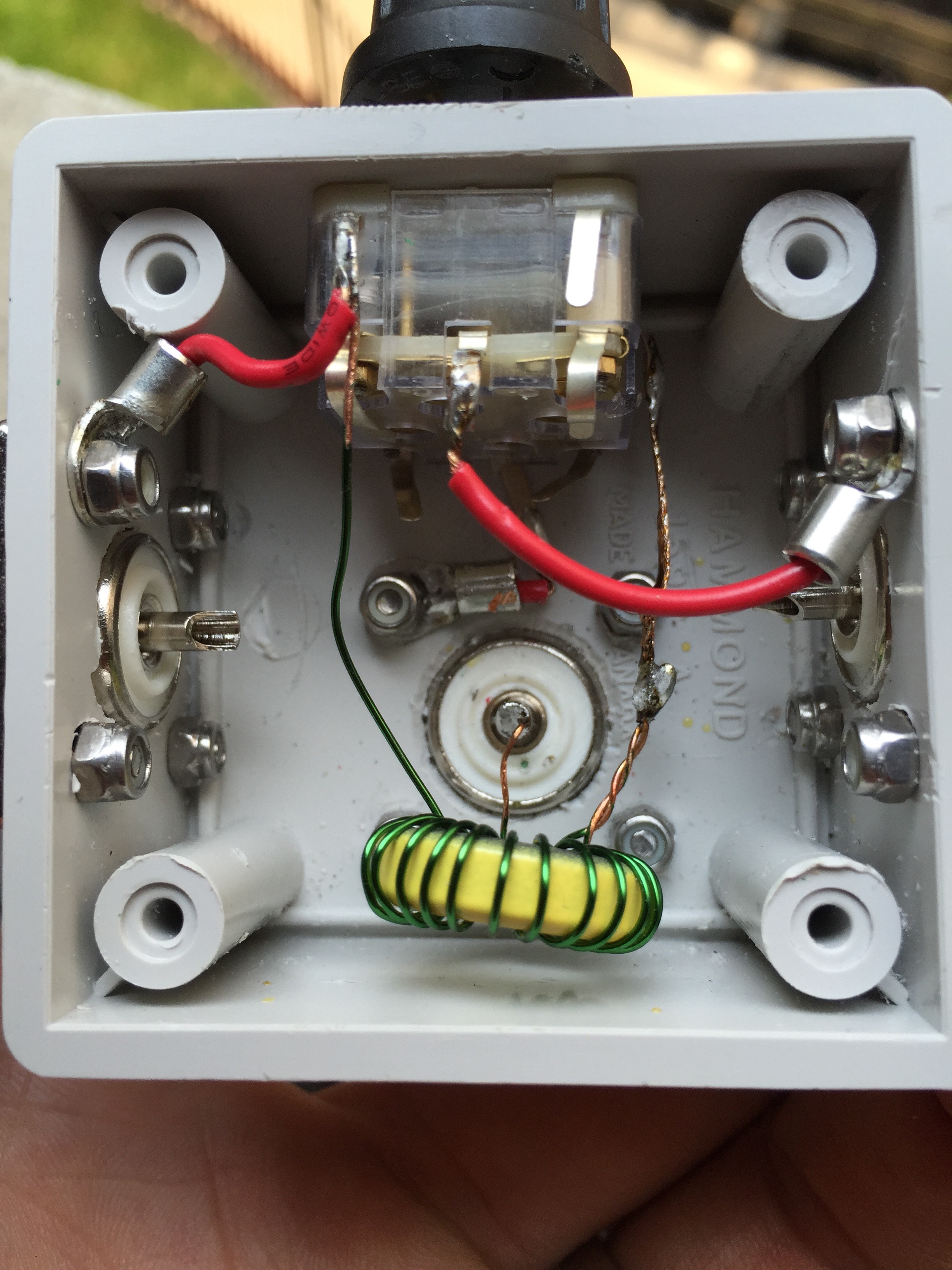
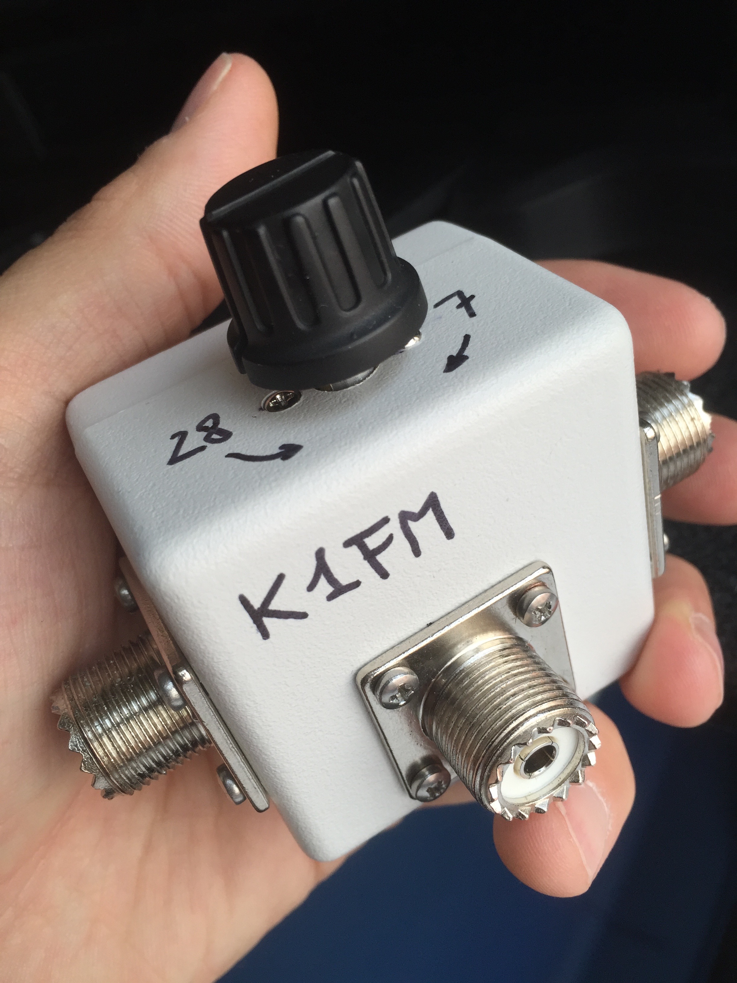
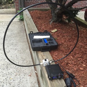
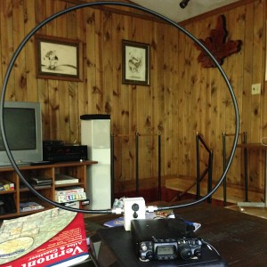
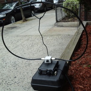
This time I used a smaller Hammond Enclosure, the 1594ASGY. The capacitor, instead, is a dual gang 266 pF by Mike’s Electronic Parts.  Both gangs are engaged in parallel as well as all the trimmer capacitors (trimmers are used to raise the minimum capacitance and also raise the maximum a little bit). By doing so, the loop covers from 40 to 10 meters. Here is the is the first test item:

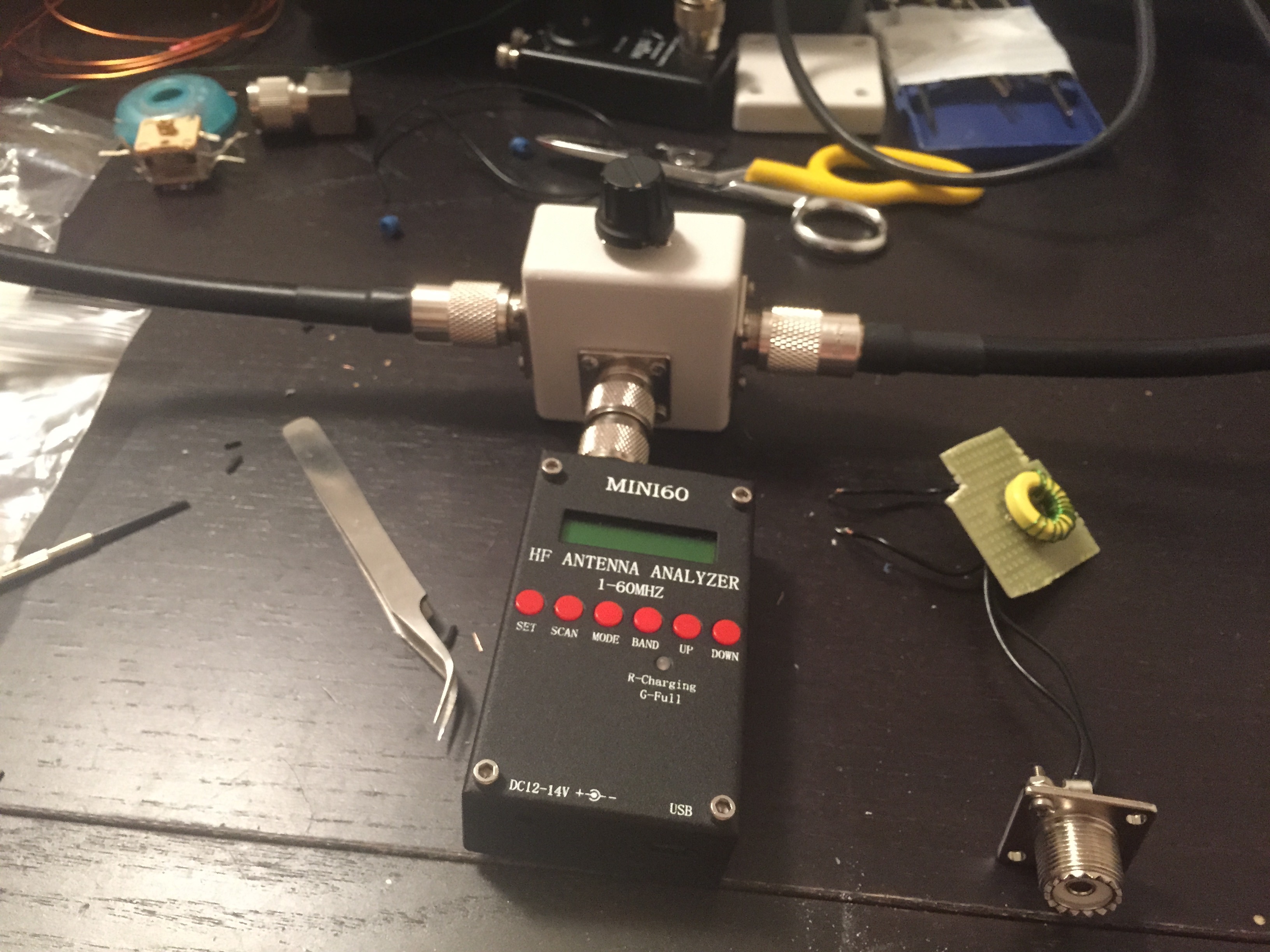
And the analyzer results:

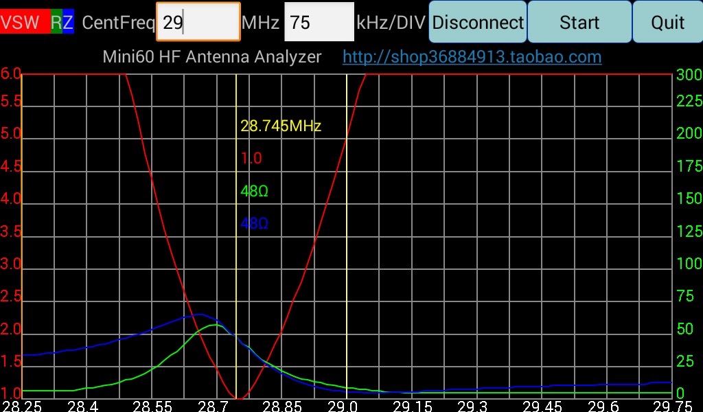
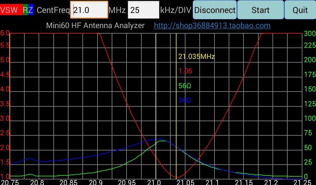
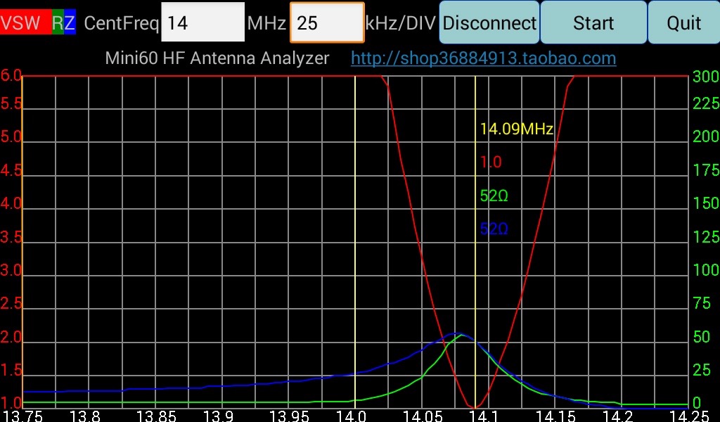
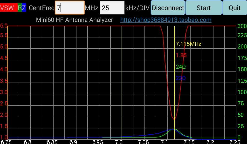
As you can see, on 20 meters and above not only the SWR is low but also the impedance is constantly around 50 ohm. No need for a second knob! On 30 and 40 meters, instead, conditions deteriorate considerably but I never expected any good performance from such a small loop on those bands anyways. Below 14 MHz I generally use my loop to listen only. It might happen to make a contact once in a while, but it is rare.

The loop responded as I wanted it to… But was it performing? To find out, yesterday I did the first field comparison of four different foldable loops:

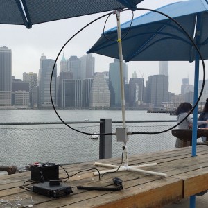
1) Toroidal Coupled Loop 6FT (the antenna I’m writing about today)
2) Army Loop 6FT (the antenna I described last time)
3) Inductively Coupled 6FT Loop (classic design, just smaller than usual)
4) Inductively Coupled 11FT Loop (the classic loop! Practically a photocopy of the Alexloop)

Testing was performed on 20 meters WSPR by sending 3 frames on each antenna starting at 7PM local time. By the time I finished with the last antenna it was already 8PM and it’s possible that during such time propagation conditions evolved. The ideal way to perform this test would be transmitting with all the antennas at the same time, but I am not equipped to do that… At least not yet!
Finally, the gathered data:

loops-shootout

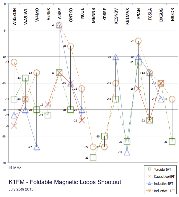
As expected, the test shows the 11FT loop constantly being on top of the game. Loop dimensions are critical and on 20 meters there is a considerable difference between 11 and 6 feet circumference. On the other hand, the 6 Feet loops (Toroidal, Capacitive and Inductive) seem to be delivering similar performances. There are no clear winners or losers, which is good news because that means I can keep using the latest version (toroidal) which is smaller and simpler to use.

Future plans include building the biggest toroidal loop possible, as well as making my 11FT inductive loop lighter and easier to transport.

Best 73’s

Alain K1FM

Categories
Hacks HF Portable

K1FM Mini Magnetic Loop

IMG_3408

Disclaimer: if not all precautions are taken, Magnetic Loops can be dangerous.
Tensions in excess of a few KV’s can and will develop even when operating at relatively low powers. Fires can also develop .Never ever touch the loop radiator during transmissions!
Moreover, the magnetic fields generated by these antennas are potentially harmful to a number of individuals, or even to yourself.
This page is for illustrational purposes only: I take no responsibilities from the harm or damage that might result from your attempts to replicate this work.

Imagine you live in a place like New York City and you want to do some radio. Chances are you might run into some of the same problems I had to face. They are:

#1: No antennas are allowed on the roof. You can’t even access the roof!
#2: Like most of the other New Yorkers, I live without a car therefore no mobile operations are possible.
#3: Over here we live face to face, shoulder to shoulder. Portable operations are possible but – for the most part of the city – forget about dipoles, random wires, end fed antennas, counterpoises and such… Forget about wires in general. This is New York City, there simply is no room to hang stuff around.

So, whats the solution to this mess? Here it is:

IMG_3409

Welcome to the magic world of magnetic loops! If you tried a loop already, then I don’t need to explain how efficient, quiet and incredibly small these antennas can be. In my specific case, this table top loop allows operations from busy Manhattan parks, Tennis courts, once I even used it in a Starbucks!

In the past I made slightly bigger ones (say 3 feet in diameter) that were better performing especially in the lower bands but they required to be supported by PVC tubing. Who wants to carry PVC around on a bicycle?!?  I said to myself: it has to be even smaller… so I made this one. It’s so small it doesn’t seem to be real… but it is! Check this video out (thanks K2COW):

Check out the /PM logbook from the past few weeks. Consider I run between 1 and 3 watt and I  only operate around 1-2 hours at a time:

2014-05-31 KK4EQB GA 10m SSB 59 52
2014-05-31 W1AW/0 MO 15m CW 59 59
2014-06-07 WW2SUB OK 20m CW 559 549
2014-06-07 WA3KEY/2 NY 15m SSB 59 52
2014-06-07 W4CU FL 15m SSB 59 52
2014-06-14 CT1EEB 15m SSB 59 59
2014-06-14 F5GPE 20m JT65 599 599


The kit travels in a custom cut hardcase and other than the antenna itself  it includes an FT-817ND with a modified internal LiPo battery, another external LiPo, a homemade USB audio interface (for PSK31 and JT65), a V/UHF vertical, the mic, a CW key and my FCC license. (Why do I carry the license? It happened twice that people called the cops on me, so I better have it ready for next time it will happen)

IMG_3540

You might have noticed that contrary to general construction principles the loop is not inductively coupled. In facts, I wanted to try a capacitively coupled one (aka army loop) because the latter does not require a coupler loop. Also, this loop is a bit smaller than I wish it was. The main idea behind this design is trading some of the performance in exchange for maximum portability.

If you kept reading down to this point you really must be interested in this so lets take a look inside! Here is the schematic diagram:

IMG_4501

And this is how I actually built it:

loop-inside

Both capacitors I used are polyvaricons. I got the single gang on Ebay for about $8 and the other one (dual gang) from  Scott’s Electronic. I believe they could resist without arching up to 10Watts (I did not try that) but they work just fine with the FT817 at 5Watts. The white enclosure is an Hammond 1594BSGY while the coax loop is composed of 6ft of LMR400 cable (NOT the Ultra-Flex version).

In this configuration the loop can operate from 30 to 10 meters. Using a two spires radiator of the same diameter it also covers 40 meters. I haven’t had a chance to check this antenna with a proper analyzer. All I know is that – depending on the band and the surroundings – SWR tends to be between zero and three bars on the FT-817 SWR meter. I also know that I had a few transoceanic contacts on 10, 15 and 20 meters in CW, FM, USB and JT65 modes. All of them using tiny LiPo batteries and Powers in the range of 2-3 Watts!

This is QRPp done using a microscopic antenna and, it goes without saying, it takes a lot of patience constance and curiosity. Sometimes I come home with nothing it the log. The day propagation goes up and I do DX.
Results are unpredictable, and that’s the beauty of it!

Update: Check out my latest portable loop!