
I really, really like magnetic loops.
After making a bit of a splash with at the Dayton Hamvention and publishing how to make your own on QST I decided to improve the design a bit more, so here I am with the latest iteration of the K1FM Magnetic Loop.
The new design improves the older one in a few key aspects:
– Entirely 3D printed
– Readily available, made in the USA variable capacitor
– Easy to assemble
Basic geometry and main electrical characteristics remain unchanged:
– 4o to 10 meters
– 125 inches radiator
– 165pF variable capacitor (dual gang series)
– QRP power (it actually can handle a lot more but, as you know, using a magnetic loop in close proximity with more than a few Watt is against FCC guidelines and potentially dangerous. Don’t do that)
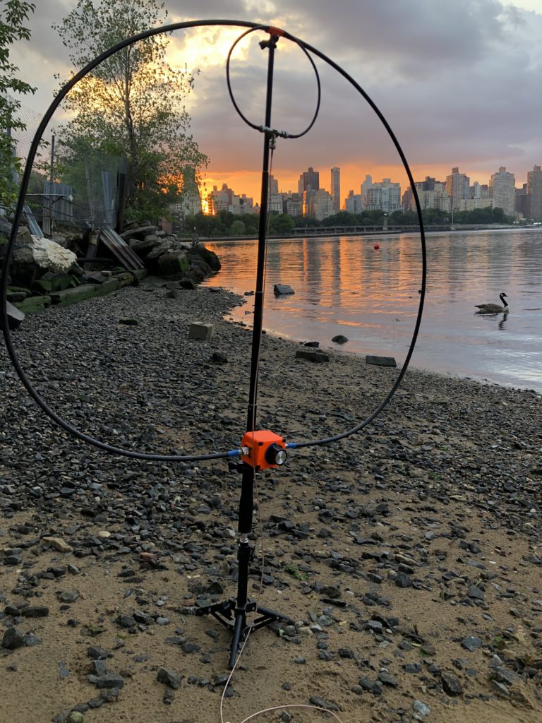
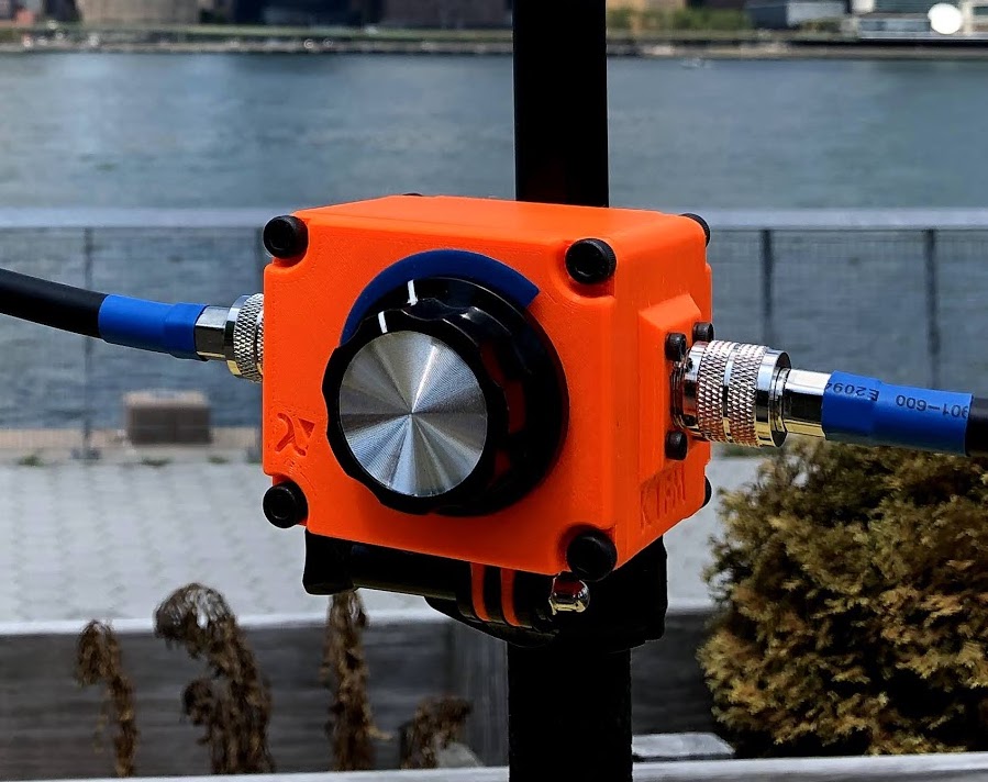
The new enclosure requires no rework in order to be mounted. It is now quickly detachable by using the same mount type as the radiator/exciter assembly. This makes the antenna even more portable and, at the same time, opens the possibility of using other support types in place of the selfie-stick (fishing rods, PVC pipes etc.).
The capacitor uses a 3:1 planar reduction that, combined with the a fairly large knob, makes tuning quick and easy. A 3D printed indicator (blue) shows the current shaft position: just by looking at enclosure you can tell where about you are currently tuned and act accordingly when it’s time to tune again.
Thanks to a new splitter design, the exciter loop is now conveniently made out of a standard LMR240 BNC-male to BNC-male pigtail. The splitter also allows the possibility of using multiple radiator/exciter assemblies in order to, for example, work 6 meters.
I also redesigned the radiator mount to follow the different bending radiuses of the radiator and the exciter loops. Both cables now snap-in with just the right amount of force, therefore zip-ties are no longer needed.
The new loop looks great and works better!
I’ve decided to call it K1FM-Loop. If you want to build your own, here are the instructions to do that